
Gated pulse descrambler
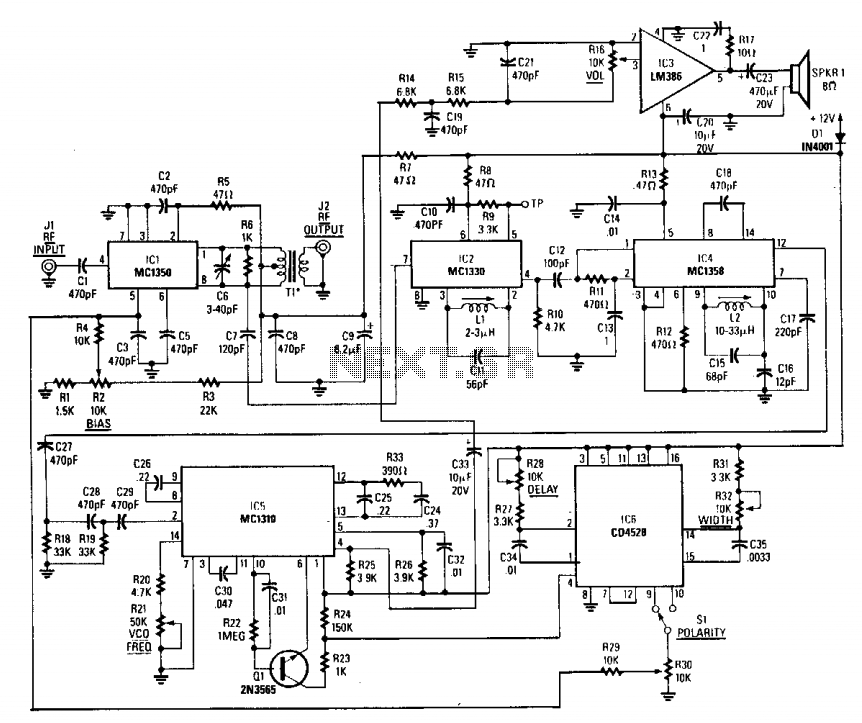
The described circuit is designed to process video signals effectively by utilizing an amplifier to boost the strength of the incoming video signal. The video detector is responsible for demodulating the video signal, extracting the necessary information for further processing. The inclusion of a second subcarrier detector is crucial for synchronization recovery, ensuring that the output signal remains aligned with the original source, which is particularly important in applications involving video transmission.
The pulse-former circuit plays a vital role in this configuration by dynamically adjusting the gain of the amplifier during synchronization intervals. This gain modulation helps to maintain signal integrity, especially during critical moments when synchronization is required. By increasing the gain during these intervals, the circuit can effectively reduce the impact of noise and interference, leading to a clearer output signal.
Furthermore, the provision for subcarrier audio descrambling adds versatility to the circuit. This feature allows for the recovery of audio signals that may be encoded or scrambled within the subcarrier frequency. By integrating this capability, the circuit can serve dual purposes: processing video signals and recovering audio, making it suitable for various applications in multimedia systems.
Overall, this circuit represents a sophisticated approach to video and audio signal processing, combining multiple functionalities into a single design that enhances performance and reliability in synchronization and signal recovery tasks.This circuit consists of an amplifier and video detector with a second subcarrier detector for synch recovery purposes. A pulse-former circuit modulates the gain of the main channel increasing it during synch intervals. Provision for subcarrier audio descrambling is also provided. 🔗 External reference
Related Circuits
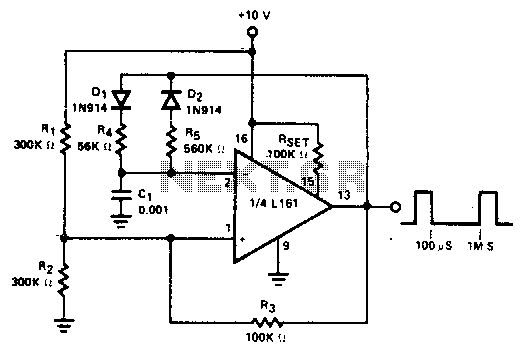
The duty cycle of the output pulse is equal to R4/(R4 + R5) x 100%. For duty cycles of less than 50%, D1 can be eliminated and R2 increased. R4(eff) is the effective value of R4 in the circuit,...
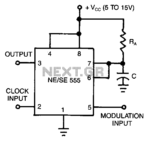
In this application, the timer operates in monostable mode. The circuit is activated by a continuous pulse train, and the threshold voltage is adjusted by the signal applied to the control voltage terminal at pin 5. This modulation of...
This circuit utilizes a dual-timer NE556 to generate 1Hz pulses spaced 5 seconds apart, with the option for manual or automatic operation. The NE556 integrated circuit (IC) consists of two independent timers. The NE556 timer is a versatile device that...
A novel method of hydrogen generation through water electrolysis utilizing an ultra-short-pulse power supply is presented. The process of hydrogen generation via water electrolysis involves the splitting of water molecules (H2O) into hydrogen (H2) and oxygen (O2) gases using electrical...

This circuit generates clean logic pulses with minimal current consumption. It is designed to produce short 2 ms pulses at a frequency of one pulse per second, drawing only 1 microamp from a 9-volt battery. The described circuit operates efficiently by...
The circuit presented on this page attempts to be an interface to convert pulses such as provided by a Basic Stamp or R/C receiver to a dual PWM (Pulse Width Modulation) signal required by an H-bridge. The simplest circuit...