
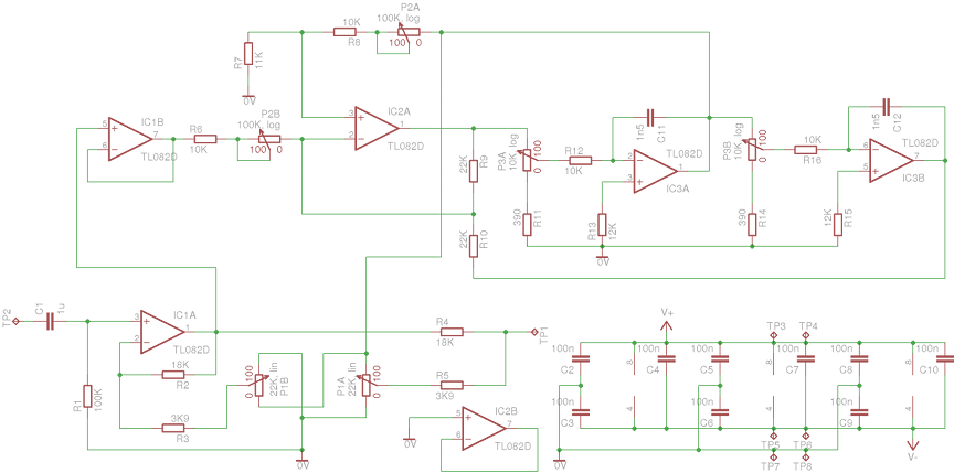
Parametric SubWoofer Equaliser
The described circuit operates on the principle of a graphic equalizer, utilizing variable simulated inductors to allow for frequency sweeping. This design incorporates four 10K potentiometers, each contributing to the adjustment of frequency response. The pots are configured to provide a range of cut and boost effects, with a neutral center position that has no impact on the signal. The maximum achievable boost and cut levels are approximately 12 to 14 dB, which is typical for such applications.
In the low-frequency section, the circuit can be adjusted to sweep frequencies from 35Hz to 150Hz when operating in peaking mode. This peaking mode is standard for parametric equalizers, allowing for precise control over specific frequency ranges. Additionally, the circuit offers a shelving option, which modifies the frequency response in a manner akin to traditional tone controls. This feature enables the user to adjust the overall tonal balance of the audio signal, providing both flexibility and enhanced control over the sound output.
The implementation of variable inductors in this circuit allows for dynamic adjustments, making it suitable for various audio applications, including live sound reinforcement and studio mixing. The ability to sweep frequencies and apply either cut or boost enhances the versatility of the equalizer, catering to diverse audio processing needs. Overall, this design exemplifies the principles of modern audio equalization, combining user-friendly controls with advanced signal processing capabilities.In essence, it uses the same principle as a graphic equaliser, but the simulated inductors are made variable, so the frequency can be swept back and forth. The four 10K pots provide cut (when on the left or anti-clockwise side of centre) or boost, and in the centre position have no effect at all.
Maximum boost and cut is about 12 to 14dB (typical). The low frequency section can be swept from 35Hz to 150Hz in peaking mode (this is the normal form of operation for a parametric equaliser), but also offers the option of shelving. Shelving is similar to the operation of conventional tone controls, but th 🔗 External reference
Related Circuits

22W into 4 Ohm power amplifier, Variable Low Pass Frequency: 70-150Hz. This unit is intended to be connected to an existing car stereo amplifier, adding functionality. The described power amplifier is designed to deliver an output power of 22 watts...
A parametric equalizer on an audio-mixer-sized PCB. The circuit design features a parametric equalizer implemented on a printed circuit board (PCB) sized for integration into an audio mixer. The equalizer allows for precise control over the frequency response of an...
The project described in this article is a constant Q, fully expandable graphic equaliser. Where most "conventional" graphic EQ circuits have a Q that is dependent on the setting of the pot, this one maintains the same Q at...
The amplifier can be assembled by a reasonably experienced hobbyist in about three hours. The metalwork will take somewhat longer, and this is especially true for the high continuous power variant. Even so, it is simple to build, compact,...
A fully parametric tube equalizer (EQ) design aims to merge two schematics into one. The goal is to create a tube-based gyrator section with adjustable Q, frequency, and gain while utilizing integrated circuits (ICs) for the input and follower...
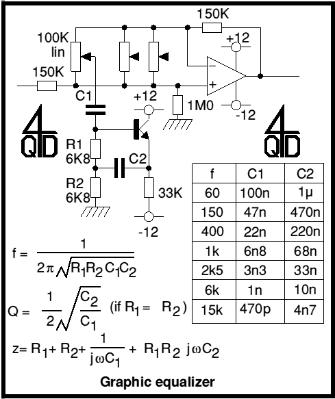
Audio graphic equalizers are very common as commercial products (for Hi-fi, car audio and stage use) but circuits for them are very rarely published. I didn't design this one but it's really very simple. The details shown are...
Warning: include(partials/cookie-banner.php): Failed to open stream: Permission denied in /var/www/html/nextgr/view-circuit.php on line 713
Warning: include(): Failed opening 'partials/cookie-banner.php' for inclusion (include_path='.:/usr/share/php') in /var/www/html/nextgr/view-circuit.php on line 713