
Expandable Graphic Equaliser circuit
The described project is a constant Q graphic equaliser utilizing Multiple Feedback Bandpass (MFB) filters. This design choice ensures that the Q factor remains consistent across various settings, a significant improvement over conventional graphic equalizers where the Q varies with the control settings. The MFB filters are integral to this design, providing a specific response to targeted frequencies while maintaining stable performance across the equaliser's range.
The architecture of the equaliser includes between 10 to 30 MFB filters per channel for stereo output, allowing for a comprehensive frequency response and precise equalisation capabilities. Each filter is carefully designed to minimize phase shift and ripple, although some trade-offs in these areas may occur when multiple sliders are adjusted simultaneously. The circuit's unique characteristic is the ability to maintain a constant Q, which enhances room equalisation and feedback reduction, making it particularly effective for demanding audio environments.
The op-amps selected for this project, such as the NE5532 and OPA2134, are chosen for their capability to drive low impedance loads, essential for the parallel configuration of the filter inputs. The circuit design includes a variable resistor (R6) that dictates the maximum boost and cut levels, with a standard value of 39kΩ allowing for a ±12dB adjustment, suitable for most applications. This feature enables fine-tuning based on specific installation requirements.
Input voltage management is critical in this design, with a maximum input rating of 1V (0dBu). An attenuator may be necessary if higher input levels are anticipated, with provisions for restoring gain through resistor adjustments. The internal gain of the U2B stage, approximately 12dB, necessitates careful input level monitoring to avoid clipping, particularly given the narrow bandwidth of the filters.
For automotive applications, special considerations are required, including the establishment of an artificial ground and adherence to lower voltage limits to prevent distortion. The overall design emphasizes versatility and adaptability, making it a valuable tool for various equalisation tasks in both home and automotive audio systems.The project described in this article is a constant Q, fully expandable graphic equaliser. Where most "conventional" graphic EQ circuits have a Q that is dependent on the setting of the pot, this one maintains the same Q at all settings. This is achieved by using MFB (Multiple Feedback Bandpass) filters, instead of the more common "gyrator" tuned circuit.
As always, there are pros and cons for the approach described here. Phase shifts tend to be a little more radical, and the passband has more ripple than a conventional circuit, but only where a number of sliders are set to boost or cut. On the positive side, specific frequencies are dealt with specifically regardless of the level, and not with a variable Q.
The constant Q circuit makes room equalisation and feedback reduction far better behaved. The filters used are the same as in the Instrument Graphic Equaliser and subwoofer equaliser (see Project 64 and Project 84), and are multiple feedback bandpass types. An example of this filter is shown in Figure 1, and more details are available from the project page for the MFB filter (Project 63).
Depending on the configuration you ultimately decide upon, you will need between 10 and 30 of these filters - per channel for stereo! This circuit is reproduced from the original article for convenience - the actual filter circuits used are slightly different, and are shown in Figure 3.
Building 60 of these may sound like an awful chore, which is perfectly reasonable, since it will be just that. With this knowledge at hand, this may go some way to help you make some. There is one thing of special note in this circuit. R6 (39k as shown) determines the maximum amount of boost and cut, and if you wanted to, you can make it variable.
With the filter circuits shown below, 39k allows a boost and cut of 12dB - which is about right in most installations. A value of 10k will allow a maximum of a little over 5dB. Any value between these limits will provide the optimum for a given environment, and this can be preset.
This is a very useful feature, and one that I believe is unique to this circuit. The slide pots are wired with all the end connections in parallel, and the "Sig" output above must drive all the filter inputs, which are also in parallel. For a 1/3 octave equaliser, this represents a load of around 800 ohms on U2B. The NE5532 was chosen as it is one of the few opamps that will drive such a low impedance. Don't be tempted to use anything that is not rated to drive such a low impedance, or it will distort because of output current limiting.
Another suitable opamp is the OPA2134 (dual), which also has a very high drive capability - there are no doubt others, but these are the ones I know about. The maximum rated input voltage is 1V (0dBu), and if you anticipate that the input will be higher than that, I suggest an attenuator at the input.
The gain can be restored by increasing the value of R8, so if a 3:1 attenuator were used at the input (10dB), then a 30k (33k would be OK) resistor in place of the 10k will bring the overall gain back to unity. Remember that U2B operates with gain (about 12dB), so the internal overload limit is lower than you might expect.
Because of the narrow bandwidth of each filter, these too can be driven into clipping if the input level is too high, and this is unlikely to improve the sound. Overall, this is a very versatile unit, and once the initial shock of construction has passed, can be used for the most demanding of equalisation tasks.
It can also be used in an automotive installation, but an artificial earth must be created, and the signal voltage limits will be reduced considerably. I suggest that the maximum input voltage be kept below 0.5V RMS - lower than this will provide a better safety margin, and will ensure that clipping does not occur regardless of slider settings.
🔗 External reference
Related Circuits
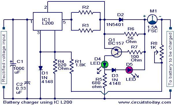
A simple battery charger circuit with reverse polarity indication is presented here. The circuit utilizes the L200 integrated circuit (IC), which is a five-pin variable voltage regulator. The charging circuit can be powered by DC voltage from either a...
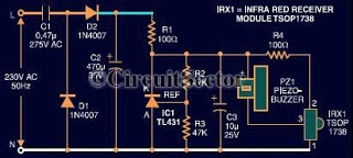
This document presents an infrared remote control tester circuit that can be constructed at a low cost. The circuit is built around the infrared receiver module TSOP1738. The state of the remote control can be observed through the sound...
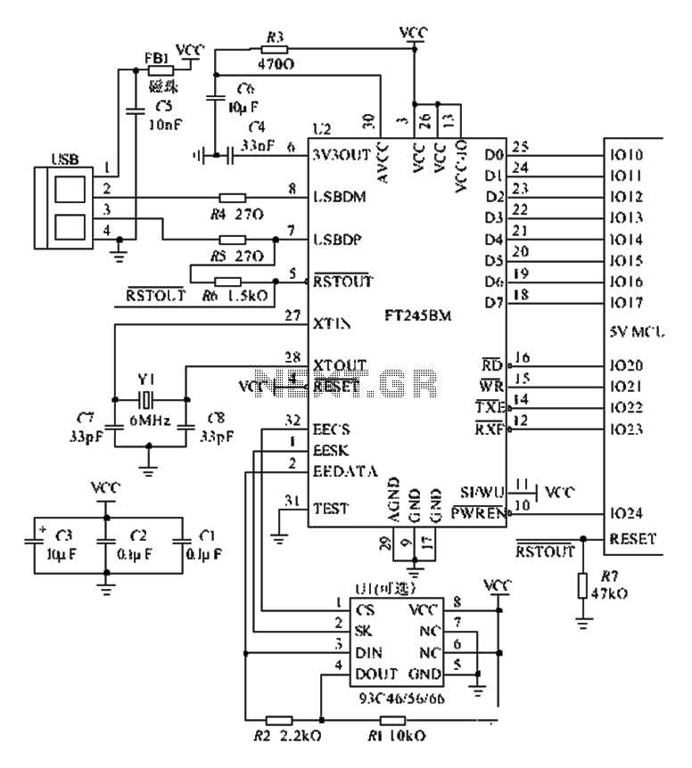
The FT245BM typical hardware circuit operates in bus-powered mode and employs a power-on reset mechanism to initialize the device. The clock circuit can be implemented using a 6 MHz crystal oscillator module or a combination of a 6 MHz...
The delay time ranges from 0.5 to 3.5 seconds, which can be adjusted using the potentiometer RP to modify the delay duration. The circuit utilizes a timing mechanism that allows for the adjustment of delay intervals between 0.5 seconds and...
If you want to try a higher voltage with your pedals, try this simple and easy voltage doubler circuit which uses an ICL7660 CMOS Voltage Converter Chip. I have found that JFETs such as the J201 sound much better...
The circuit diagram of an IC Controlled Emergency Light with Charger, also known as a 12V to 220V AC inverter circuit, is presented here. This circuit features automatic activation of the light during mains failure and includes a battery...
Warning: include(partials/cookie-banner.php): Failed to open stream: Permission denied in /var/www/html/nextgr/view-circuit.php on line 713
Warning: include(): Failed opening 'partials/cookie-banner.php' for inclusion (include_path='.:/usr/share/php') in /var/www/html/nextgr/view-circuit.php on line 713