
PC FM Radio circuit
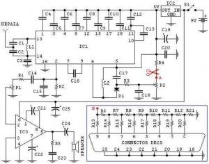
The FM radio receiver circuit is designed to facilitate the reception of FM signals, allowing users to listen to radio broadcasts through a personal computer. The circuit typically consists of several key components, including an antenna, a radio frequency amplifier, a demodulator, and audio output stages.
The antenna captures the FM signals, which are then amplified by the radio frequency amplifier to ensure a strong enough signal for processing. The demodulator extracts the audio information from the modulated carrier wave, converting it into an audio signal. This audio signal is subsequently passed to the audio output stage, where it can be further amplified and sent to speakers or headphones.
The inclusion of potentiometers P1 and P2 provides user control over the audio output and frequency tuning, respectively. P1 allows for the adjustment of sound intensity, enabling the listener to set a comfortable volume level. P2 permits fine-tuning of the reception frequency, allowing users to lock onto their desired radio station more accurately.
For those interested in integrating this circuit with a PC for frequency monitoring, additional components may be required, such as a microcontroller or an analog-to-digital converter (ADC). These components can facilitate the digital representation of the received signal, enabling real-time frequency analysis and visualization on the computer.
This FM radio receiver circuit is versatile and can be adapted for various applications, including educational projects, hobbyist experiments, or as a foundational element in more complex audio systems. Proper assembly and tuning of the circuit will yield optimal performance, allowing users to enjoy high-quality FM radio reception.This is a fm radio receiver circuit which can be used with PC.PC radio REGULATIONSA) With the P1 we regulate the intensity of sound.B) With the P2 we regulate the frequency of reception.C) Optionally: If you want to check the frequency with your PC it will be supposed you make the following energies:- You assemble and the circuit that is in the blue frame.-.. 🔗 External reference
Related Circuits
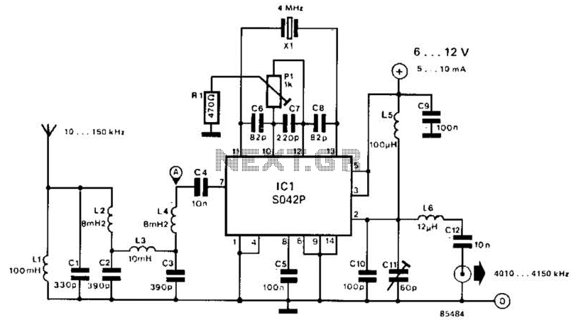
This converter shifts frequencies from 10 kHz to 150 kHz up to 4.01 to 4.15 MHz, suitable for use with a shortwave receiver for very low frequency (VLF) reception. A 4 MHz local oscillator frequency is utilized, and the...
Approximately one watt RMS appears to be a suitable output level, which is also the maximum power that a basic amplifier powered by 12V can deliver to an 8 Ohm speaker. A very low saturation amplifier may reach up...
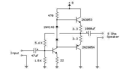
This weblog focuses on electronic circuit schematics, PCB design, DIY kits, and electronic project diagrams. The following describes a small audio amplifier, similar to those found in medium-sized transistor radios. The input stage is biased to ensure equal power...
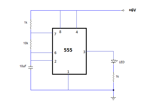
The NE555 is one of the most commonly used timer integrated circuits (ICs). It is a monolithic timing circuit capable of producing accurate and highly stable time delays or oscillations. Similar to general-purpose operational amplifiers, it is reliable, easy...
I have been researching a "mystery circuit" and I cannot determine its name. Assistance is requested. The inquiry pertains to an unidentified electronic circuit, often referred to as a "mystery circuit." Such circuits can encompass a wide range of configurations...
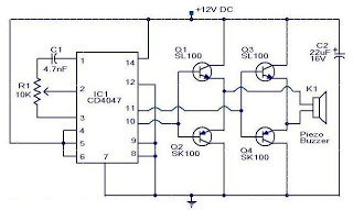
This is a small circuit designed as an insect repellent, targeting mosquitoes and birds by producing high-frequency audio signals. These signals interfere with the hearing of insects, making it unbearable for them, causing them to flee. The operation of...