
Vlf Converter Circuit
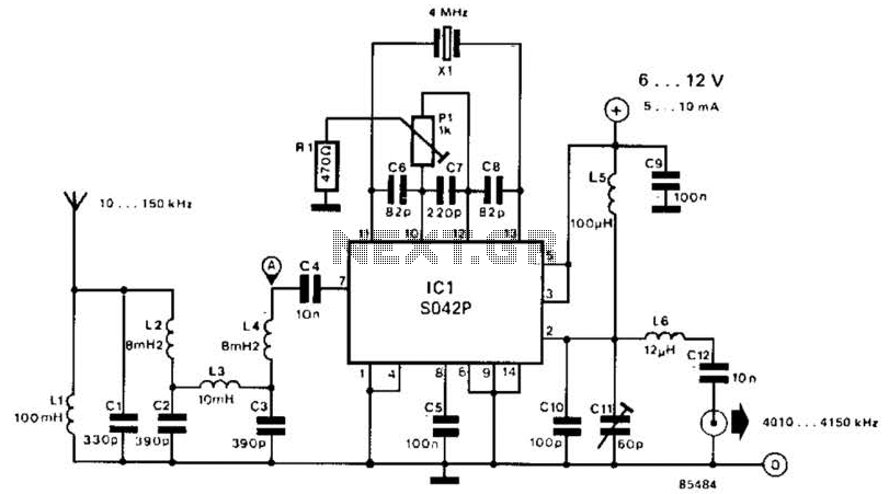
The frequency converter is designed to enable the reception of signals in the VLF range, typically used for various communication and navigation applications. The circuit employs a frequency mixing technique, where the input signal within the 10 kHz to 150 kHz range is combined with a local oscillator signal at 4 MHz. This mixing process generates new frequencies, specifically the desired output range of 4.01 to 4.15 MHz.
The circuit includes the following key components:
1. **Antenna**: A long antenna is essential for optimal reception of VLF signals. The length of the antenna should ideally be a quarter wavelength of the lowest frequency of interest to enhance sensitivity and reduce noise.
2. **Crystal Oscillator (XI)**: The crystal oscillator serves as the local oscillator for the mixer circuit. It generates a stable 4 MHz signal that is crucial for accurate frequency conversion. The choice of crystal can influence the stability and performance of the converter, and therefore, selecting a microprocessor crystal or another suitable type is recommended.
3. **Mixer Circuit**: The core of the converter is the mixer, which combines the input VLF signal with the 4 MHz oscillator signal. This component can be implemented using various technologies, including diode mixers or integrated circuit mixers, depending on the desired performance characteristics and complexity of the design.
4. **Output Filtering**: After mixing, the output signal may contain unwanted frequencies (harmonics and sidebands). A band-pass filter is typically employed to isolate the desired frequency range of 4.01 to 4.15 MHz, ensuring that only the relevant signals are passed to the shortwave receiver.
5. **Amplification**: To enhance the signal strength before it reaches the receiver, an amplifier stage may be included. This stage is crucial for maintaining signal integrity and improving the overall sensitivity of the receiver system.
The overall design should prioritize minimizing noise and distortion to ensure clear signal reception. Proper PCB layout techniques and grounding practices should be employed to avoid interference from other electronic components. This frequency converter is a versatile tool for expanding the capabilities of shortwave receivers, enabling them to capture a broader range of frequencies effectively. This converter converts 10 kHz to 150 kHz to 4.01 to 4.15 MHz 1`or use with a shortwave receiver for VLF reception. A 4-MHz L.. frequency is used. XI can be a microprocessor XTAL or another suitable type. The antenna should be as long as possible. 🔗 External reference
Related Circuits
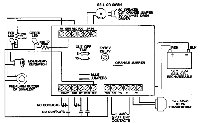
The following alarm circuit is designed with features that may be suitable for residential and commercial alarm system applications. It has a 12V and 1.5A regulated power supply. Furthermore, this residential alarm circuit also includes a delay circuit, a...
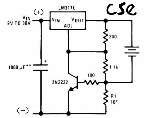
This is a straightforward charger designed for 9V to 30V batteries, primarily operated by the IC LM317L and a 2N222 transistor. It utilizes direct input DC voltage, and a recommended capacitor of 1000µF is included for filtering the output...
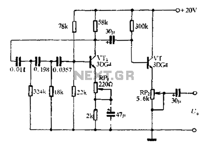
1 kHz RC phase shift oscillator circuit The 1 kHz RC phase shift oscillator circuit is designed to generate a continuous sine wave output at a frequency of 1 kHz. This circuit typically utilizes a combination of resistors and capacitors...

The Infrared IR Receiver circuit consists of a phototransistor, a microcontroller, and an amplifier. Understanding the data transfer between these three components is essential for successfully operating the circuit. The phototransistor receives digitally encoded data from an IR emitting...
Make the following connections: GND (pin 8) to ground, Vcc (pin 16) to 5V, OE (pin 13) to ground, MR (pin 10) to 5V. This setup makes all of the output pins active and addressable at all times. The...
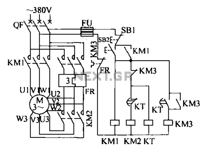
The extended delta decompression starter is designed to manage the operation of a three-phase motor during startup. It involves the initial connection of the motor's three-phase winding set to facilitate a reduced voltage startup, which is achieved through a...