
ph electrode circuit

The pH measurement circuit described utilizes a pH electrode, which is a specialized sensor designed to detect the activity of hydrogen ions in a solution. The electrode comprises a glass membrane that selectively interacts with H+ ions, producing a voltage proportional to the pH level of the solution. This voltage is typically bipolar, oscillating around zero volts, which poses challenges for interfacing with single-supply systems.
The design incorporates an operational amplifier (U1) configured to offset the pH signal by introducing a stable bias of 512 mV. This offset is generated using the LM4140A-1.0 voltage reference, which ensures precision and stability in the output voltage. The resistor divider network, consisting of two 10 kΩ resistors, effectively halves the reference voltage to achieve the desired offset.
The output of U1 is connected to the reference electrode of the pH sensor, allowing the sensor to operate with a bias that shifts its output range. This is critical in applications where the measurement system is powered by a single supply, as it ensures that the signal remains within the acceptable voltage range for further processing.
The second operational amplifier (U2) serves as a buffer, configured again in a unity-gain mode. This configuration is essential for maintaining high input impedance, which minimizes loading effects on the pH electrode. By buffering the output, the circuit enhances compatibility with various measurement instruments, particularly those with lower input impedance that might otherwise distort the signal.
The design allows for flexibility in applications where the output voltage from the pH electrode may need to be amplified. If required, additional gain can be introduced by integrating external resistors into the feedback loop of U2, thereby tailoring the output signal to meet specific measurement requirements.
Overall, this circuit design effectively addresses the challenges associated with measuring pH levels in various solutions, ensuring accurate and reliable readings while maintaining compatibility with a range of instrumentation.A pH electrode measures hydrogen ion (H+) activity and produces an electrical potential or voltage. The operation of the pH electrode is based on the principle that an electric potential develops when two liquids of different pH come into contact at opposite sides of a thin glass membrane. This is a design circuit for the measurement. This is the figure of the circuit. Amplifier U1 off sets the pH electrode by 512 mV. This is achieved by using National`s LM4140A-1. 0 precision micro power low-dropout voltage reference that produces an accurate 1. 024V. That voltage is divided in half to equal 512 mV by the 10 k © resistor divider. The output of amplifier U1, which is set up in a unity-gain configuration, biases the reference electrode of the pH electrode with the same voltage, 512 mV, at low impedance. The pH-measuring electrode will produce a voltage which rides on top of this 512 mV bias voltage. In effect, the circuit shifts the bipolar pH-electrode signal to a uni-polar signal for use in a single-supply system.
The second amplifier U2 is set up in a unity-gain configuration and buffers the output of the pH electrode. Again, a high-input impedance buffer between the pH electrode and the measurement instrument allows the circuit to interface with a greater variety of measurement instruments including those with lower input impedance.
In most applications, the output voltage of the pH electrode is high enough to use without additional amplification. If amplification is required, this circuit can easily be modified by adding gain resistors to U2. 🔗 External reference
Related Circuits
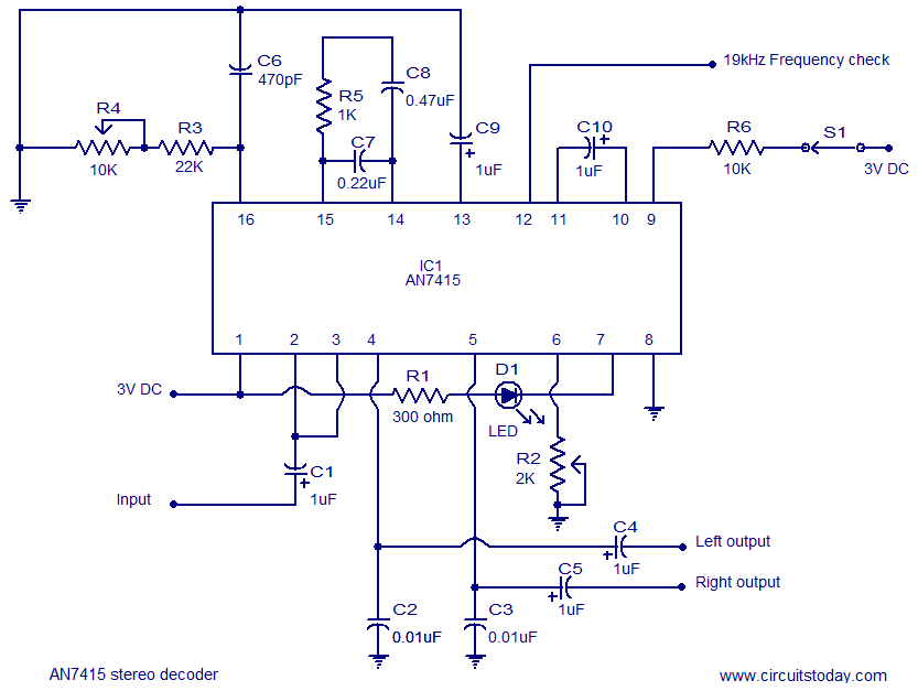
AN7415 based FM stereo demodulator circuit. 1.6 to 7V operating voltage range. High gain and low distortion. The AN7415 is a versatile integrated circuit designed for FM stereo demodulation applications. This circuit operates within a voltage range of 1.6 to...
The file being accessed no longer exists. It may have been renamed or removed from the archive. Navigation links are available on the left to browse the desired area of the archive. The connection is to cdn.preterhuman.net, which mirrors...
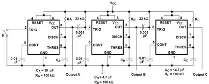
A sequential timer circuit device is utilized in various applications for initializing conditions during start-up or for activating test signals in sequences, such as in test equipment devices. The circuit diagram below illustrates a sequencer circuit with potential applications...
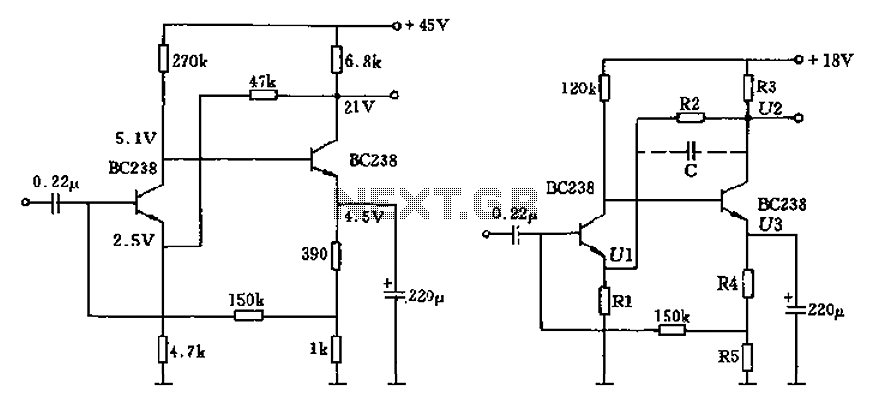
The circuit characteristic involves the elimination of external input resistors, which reduces the influence on the stabilization of the working point. It also employs two DC negative feedback loops. Additionally, the output from the second stage connects to the...
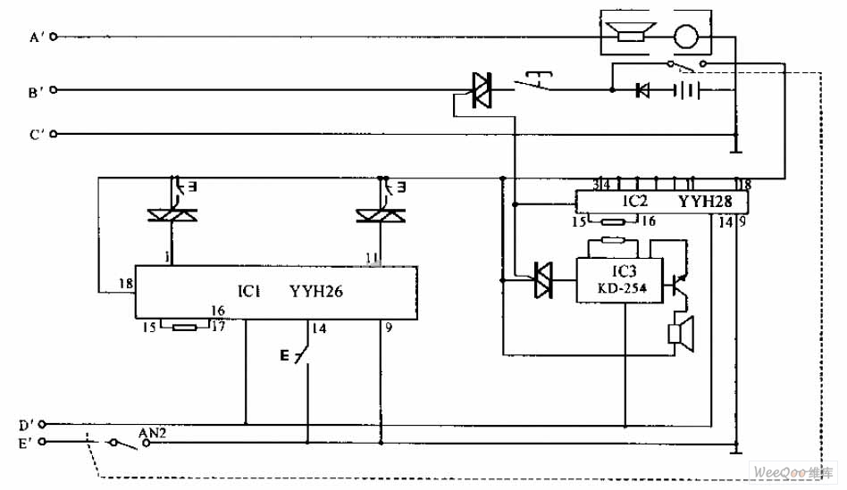
The internal telephone circuit is depicted below. By making minor enhancements to a toy telephone, it can be transformed into a functional internal telephone. This device comprises several components, including the phone unit, a decoding circuit, a ringing circuit,...
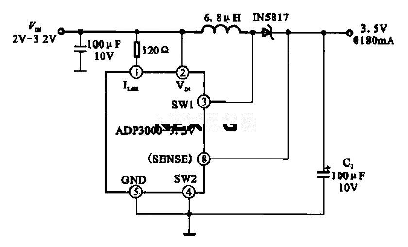
Boost 3.5V regulator circuit. This chip can boost or create a stable voltage supply from approximately 3V DC to a DC voltage of 3.5V. The boost regulator circuit is designed to increase a lower DC voltage, specifically from around 3V...