
Photo Inverting
The circuit design incorporates essential components for effective photodetection and LED indication. Phototransistors serve as the primary sensing elements, responding to changes in light intensity. The selection of resistor values is critical for ensuring optimal performance, particularly in varying lighting conditions. The circuit's flexibility is enhanced by the ability to adjust detection levels, making it suitable for diverse applications.
The inclusion of open collector outputs allows for easy interfacing with other components and systems, facilitating integration into larger projects. The design's ability to operate without a regulated power supply simplifies implementation, while the maximum voltage rating ensures compatibility with standard power sources.
The PCB layout is designed for ease of assembly and maintenance, with clearly defined input and output sections. The use of multiconductor cables aids in organization, reducing the risk of wiring errors during installation. The option to replace output resistors with jumper wires provides further customization, allowing users to tailor the circuit to specific needs.
Overall, this circuit represents a robust solution for light detection and signaling, with an emphasis on adaptability, ease of use, and efficient performance.For phototransistors a value of 470K ohms will work for most room light situations. If the light is dim, selecting a higher value resistor such as 1 Megohm will give better sensitivity. This High Impedance Test Voltmeter circuit can also be used for testing phototransistors installations.
For CdS photocells it is usually best to install the cell and then measure its resistance under the normal lighting conditions. A resistor with a value that is 3 to 5 times the measured resistance of the cell is then selected for R1. A 1K ohm resistor will allow about 10 milliamps to flow through a typical LED if the supply voltage is 12 volts.
The value of the resistors at the outputs of the comparators can changed depending on the desired current through the LEDs. The following diagram shows the circuit that is on the printed circuit board. There are 8 independent photodetectors with open collector outputs that can sink up to 15 milliamps each.
The detection voltage level for the circuit as shown is set at 1/2 of the supply voltage. If a lower or higher detection level voltage is needed, the values of resistors R9 / R10 and R19 / R20 can be adjusted. This circuit does not need a regulated power supply and can operate on supply voltages of up to 32 volts.
For more general information on Voltage Comparators please see the Voltage Comparator Information page at this site. The 1K output resistors can be replaced by jumper wires if they are not needed such as for inputs to control or signals circuits that have their own current limiting resistors.
WARNING - If the polarity of the power supply for this circuit is reversed or the circuit is connected to an AC or DCC source this circuit will be damaged. The maximum supply voltage for this circuit is 15 Volts. The diagram above can be printed in the center of a sheet of paper then and used to record wiring connections when installing the circuit, sensors and LEDs.
This diagram will be easier to use than the actual schematic for the circuit board. The following schematic is for a typical installation circuit using phototransistors and LEDs. Multiconductor cable can be used to keep the wiring runs neat as sensors and indicators are likely to used in localized groups. The following is an assembled example of the circuit board which is 2 inches by 3 inches and is drilled to fit DigiKey part ED1601 - 2 position and ED1602 - 3 position terminal blocks.
The INPUTs of the detectors are on the left and the OUTPUTs are on the right side of the picture. As in the full circuit schematic, the INPUTs and OUTPUTs of the detectors are directly across from each other on the circuit board. The following is a parts list for a typical parts list for use with the 8 - Photodetector circuit board.
The values of the resistors can be changed to suit the needs of the user. T42-1 Push-In Terminals can be substituted for the terminal blocks to reduce costs if desired. The DigiKey part number for the T42-1 Terminals is V1069-ND. To reduce the current require, the LEDs can be wired in series so that four LEDs use the same amount of current as one LED. In the example shown, approximately 8 milliamps. Infrared light is not visible to the naked eye, however, a digital camera can be used to view the IR light if it does not have an IR blocking filter on the lens.
When installing the components on the circuit board start with parts with the lowest height and work up to the tallest parts. For example starting with the diodes then resistors, IC`s, transistors, capacitors and terminal blocks.
Needle nose pliers are used to hold the wire while it was wrapped around the lead. Any excess wire can be trimmed away after soldering and the end tucked into the phototransistors lead. A small heat sink could also be used during soldering. (The out-of-focus line entering from the left in the fourth image is the solder. ) 🔗 External reference
Related Circuits
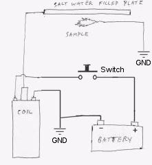
Instructions for constructing a simple Kirlian effect camera to capture high voltage corona discharges around objects, also referred to as aura photography. The Kirlian effect is a phenomenon where high voltage electrical discharges create a visual representation of the energy...
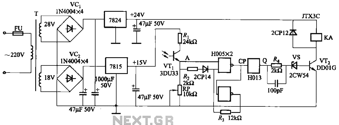
The circuit features a robust anti-jamming capability, making it suitable for demanding applications. It includes a phototransistor (VTi), a Schmitt trigger (H005), a JK flip-flop (H013), a power amplifier circuit, a relay (KA), and various actuators and other components....
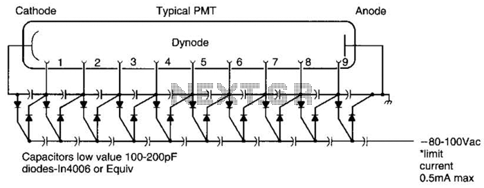
A Cockcroft-Walton voltage multiplier provides the necessary stepped voltage for the dynodes of the photomultiplier tube (PMT) without the use of a power-wasting voltage-divider resistor, which is typically employed in traditional configurations. The Cockcroft-Walton voltage multiplier is a type of DC-DC...

The optical control circuitry for high-performance street lighting is depicted in the figure. The circuit comprises a photoelectric conversion element, specifically a Light Dependent Resistor (LDR), a comparator circuit using an integrated circuit (IC1) which is a 555 timer,...
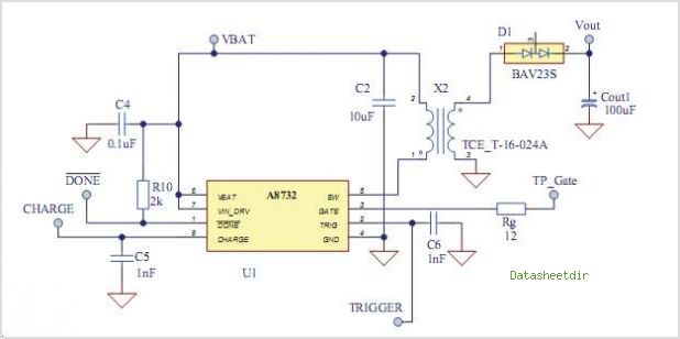
The AAT1265 evaluation board serves as a platform for testing and evaluating the AAT1265 low voltage 2MHz step-up regulator. This evaluation board illustrates the recommended size and arrangement of external components necessary to maintain output voltage regulation for up...
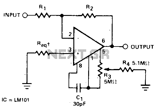
The required resistance (Req) may be zero or equal to the parallel combination of resistors R1 and R2 to achieve minimum offset. The circuit configuration described involves the use of two resistors, R1 and R2, connected in parallel. In a...