
Photodiode Alarm

The photodiode-based alarm system operates through a sequence of events triggered by the interruption of a light beam. The photodiode, when exposed to the laser or IR light, allows current to flow, which is essential for the operation of the entire circuit. The reverse bias configuration of the photodiode enhances its sensitivity to light changes, making it effective for detecting beam interruptions.
Transistor T1 plays a crucial role in the circuit. When the photodiode conducts, T1 is activated, pulling the reset pin of IC1 low, which inhibits the oscillation. The astable oscillator, configured within IC1, generates a square wave output when enabled. This output is responsible for driving the alarm speaker, producing audible signals that alert individuals to the breach of the protected area.
The design includes additional components such as resistors and capacitors that determine the frequency and duty cycle of the output pulses from the astable multivibrator. The use of variable resistor VR1 allows for fine-tuning of the oscillation frequency, enabling customization of the alarm tone.
For the IR transmitter circuit, the inclusion of black tubes around the IR LEDs serves to focus the emitted light, enhancing the effective range of the transmitter. This design consideration ensures that the IR rays can reach distances of up to 5 meters, providing flexibility in the placement of the alarm system and the protected area.
Overall, this photodiode-based alarm system is a practical solution for security applications, leveraging simple electronic components to create an effective and reliable detection mechanism.This Photodiode based Alarm can be used to give a warning alarm when someone passes through a protected area. The circuit is kept standby through a laser beam or IR beam focused on to the Photodiode. When the beam path breaks, alarm will be triggered. The circuit uses a PN Photodiode in the reverse bias mode to detect light intensity. In the prese nce of Laser / IR rays, the Photodiode conducts and provides base bias to T1. The NPN transistor T1 conducts and takes the reset pin 4 of IC1 to ground potential. IC1 is wired as an Astable oscillator using the components R3, VR1 and C3. The Astable operates only when its resent pin becomes high. When the Laser / IR beam breaks, current thorough the Photodiode ceases and T1 turns off. The collector voltage of T1 then goes high and enables IC1. The output pulses from IC1 drives the speaker and alarm tone will be generated. A simple IR transmitter circuit is given which uses Continuous IR rays. The transmitter can emit IR rays up to 5 meters if the IR LEDs are enclosed in black tubes. 🔗 External reference
Related Circuits
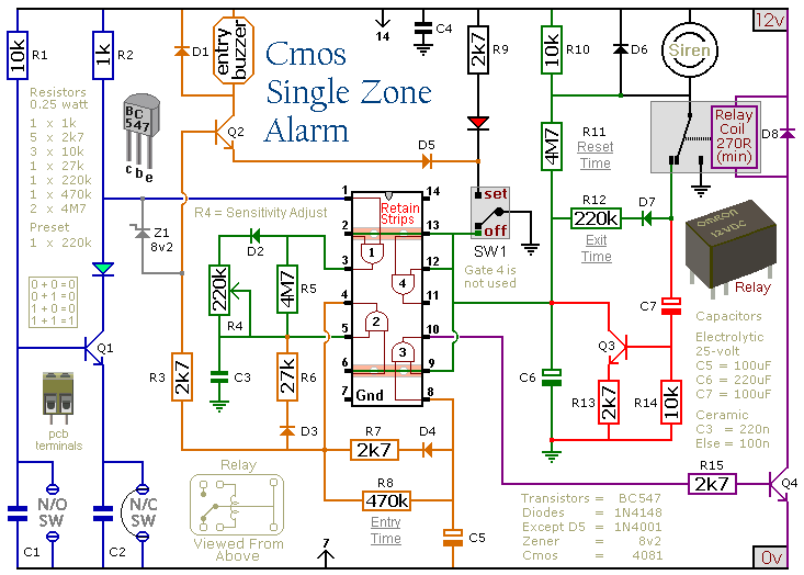
This circuit features automatic Exit/Entry delays, timed Bell Cut-off and System Reset. It has provision for normally open and normally closed switches and will accommodate the usual input devices such as Foil Tape, Pressure Mats, Magnetic Reed Contacts, Passive...

This FM radio-controlled anti-theft system can be used with any device operating on a 6 to 12-volt DC power supply. The mini VHF FM transmitter is installed in the vehicle at night when it is parked in the driveway...

This alarm features both open-loop and closed-loop detection systems along with an automatic alarm shutoff mechanism. It provides a 15-second delay for exit and entrance. Additionally, the alarm activation time can be adjusted from 1 to 15 minutes. The alarm...

IC1 generates a pulse that modulates the 1000-Hz tone generated by IC2. This circuit can be used to generate warning or alert signals. The circuit described consists of two integrated circuits (ICs), where IC1 is responsible for generating a pulse...

After the SCL line is high, the SDA line must be held low to indicate that the data being transmitted is legally binding. The data can only change when the SCL line is low. During the transfer of a...

The circuit incorporates automatic exit and entry delays, a timed bell cut-off, and a system reset feature. It accommodates both normally-open and normally-closed switches and is compatible with standard input devices such as pressure mats, magnetic reed contacts, foil...