
phototransistor Light sensor using Photo Transistor
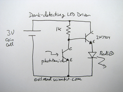
This circuit employs a phototransistor as a light-sensitive switch, functioning by controlling an LED based on ambient light levels. The phototransistor operates in a manner where it detects light intensity; in darkness, it allows current to flow and illuminates the LED, while in light conditions, it ceases current flow and turns off the LED.
The basic components of this circuit include a phototransistor, a current-limiting resistor for the LED, and a base resistor for the phototransistor. The phototransistor typically features two terminals: the collector and emitter. The base terminal, although not always present in all designs, can be utilized to bias the transistor, enhancing its sensitivity to light.
In this specific implementation, a suitable resistor value is crucial to ensure the correct operation of the LED without exceeding its maximum current rating. A common choice is to use a resistor value around 22k ohms for the base connection, which allows adequate base current while preventing excessive LED current. The gain of the phototransistor, typically around 400 for a BC337 type, means that a small base current can control a larger collector current, enabling the LED to operate effectively.
For practical application, the circuit is powered by a low-voltage source, such as a CR2032 coin cell battery, which is advantageous due to its high internal resistance. This configuration minimizes the risk of damaging the LED, as the battery cannot supply excessive current.
When designing the circuit, it is essential to ensure the correct orientation of the phototransistor and to verify all connections on the breadboard. If the circuit does not perform as expected, adjustments to the resistor values may be necessary to achieve the desired sensitivity and functionality.
In conclusion, this light-sensitive switch circuit utilizing a phototransistor is a straightforward yet effective application for controlling an LED based on ambient light conditions, with careful attention needed to component values and connections for optimal performance.A circuit which utilizes a photo-transistor to make a light sensitive switch that is when there is no light in room, the led connected to the photo-transistor lights up and when there is light in room, the led connected to Phototransistor turns off Any schematic or circuit diagram would be really helpful. Here is my Implementation on breadboard. Please tell me if this is correct. I tried to make the two lines in parallel. I suspect my connectionof base of the transistor with resistor is wrong, correct me if I am wrong. SORRY I DID NOT HAVE ANY OTHER SOFTWARE TO SHOW MY IMPLEMENTATION SO PLEASE NEVER MIND :). What did you already try and how didn`t it work What resources have you read (vedor app notes, etc. ) and in what way weren`t they clear The Photon Jun 21 `12 at 15:44 PhotoTransistor has 3 legs, emitter, base, collector, where as it has two and the resulting circuit picture doesn`t have phototransistor, it has 2 leg led type sensor Umer Farooq Jun 21 `12 at 16:04 @UmerFarooq, Phototransistors normally have 2 legs, Emitter and collector. Carriers are not injected through the base connection but instead from the light shining there. Is it possible that your phototransistor gives you a base connection to allow you to bias the transistor and then use the light to increase on top of a DC large signal Bias I have used Phototransistors before with only 2 pins multiple times.
Kortuk™ Jun 21 `12 at 16:07 EDIT - the breadboard circuit you have added looks correct (though it`s hard to read. ) so go ahead and try it. If it doesn`t work let us know. Maybe change the resistor to 2k or larger if you are worried about blowing the LED. Just to note this circuit will work fine, although Steven`s suggestion is "preferable" in general. I would maybe not change things till you have it working. The reason the circuit is usually not the best way to do this is because it relies upon Hfe, which can vary quite widely in a transistor and is subject to temperature changes.
This means the base resistor must be chosen according to the particular transistor used. The reasons it is picked for this circuit are as it uses 1 less resistor (for size purposes, see picture below) Also this circuit is designed for a 3V cell like a CR2032, which has a high internal resistance and generally cannot supply enough current to damage the LED (so it`s like having a series resistor in place) The original project page explains all this. So if you are intending to eventually power this circuit from something else other than a coin cell, then you should go for the common emitter circuit Steven describes.
The site you got the above circuit from also has an example of such a circuit: To help with the breadboard I just threw together the little circuit shown in your question. I only had an IR phototransistor but it doesn`t matter much for this, it still works the same. Anyway here are a couple of pictures of it working, hopefully you can see how the connections go: The phototransistor base is floating, and I swapped the 1k for a 22k in my circuit to bias it correctly (I arrived at this value roughly, see below) and used a BC337 npn.
Since the BC337 has lots of gain the 22k works well for the base current. To give an idea of why the 22k resistor, the BC337 I`m using has a gain of around ~400, and the voltage it will see is 3V - (Vled + collector-emitter drop) -> 3V - (1. 8V + 0. 7V) = ~0. 5V. So 0. 5V / 22k = 23uA into the base. The gain for the BC337-40 is typically 400, so 23uA * 400 = 9. 2mA. The min/max gain given in the datasheet is 250-630, so the actual max LED current could vary from ~6mA to 14mA, which is within maximum LED current (20mA) My actual measured maximum current was 10mA, so this fits with the above calculations.
It actually works very well, off in normal light and starts turning on as soon as I start dimming the lights. You may have to try a few different values of resistor i 🔗 External reference
Related Circuits

A dual-tone model train horn/sound generator/simulator circuit can be created using two NE 555 timers connected in cascade. However, the circuit diagram presented is designed with the NE 556 integrated circuit, which essentially comprises two 555 timers in a...

Physicians and repair engineers frequently utilize small light pens for visual examination purposes. Although these pens are rugged and can be expensive, their vulnerability lies in the bulb, which is a replaceable component. In practice, this often translates to...
A rear fog lamp is mandatory for trailers and caravans to enhance visibility during foggy conditions. When the fog lamp is activated, the fog lamp of the towing vehicle must be turned off to prevent distracting reflections. To achieve...
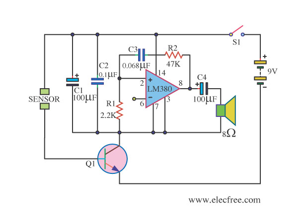
This is a water sensor alarm circuit designed to warn users about water levels. It activates an audible alarm when the sensor comes into contact with water, such as during rainfall. The water sensor alarm circuit functions primarily as a...

This circuit demonstrates the utilization of a standard LED as a light sensor. It leverages the photovoltaic voltage generated across the LED when exposed to light. The circuit operates on the principle that an LED can function as a photodiode,...

This small device is designed to jam remote controls by directing it at the TV. The circuit utilizes a 555 timer configured as an astable multivibrator, generating a frequency of approximately 38 kHz, which corresponds to the frequency at...