
Water Sensor Alarm using LM380

The water sensor alarm circuit functions primarily as a detection mechanism for water presence. It typically consists of a water level sensor, a microcontroller or comparator circuit, and an audio alarm module. The sensor is often made up of conductive materials that complete a circuit when submerged in water, triggering the alarm.
When the sensor detects water, it sends a signal to the microcontroller or comparator, which processes the input. If the water level is above a predetermined threshold, the microcontroller activates the audio alarm, which can be a buzzer or speaker, producing a loud warning sound to alert individuals in the vicinity.
The circuit can be powered by a standard voltage source, such as a battery or a wall adapter, ensuring it remains operational during critical situations. Additional components may include resistors for current limiting, capacitors for noise filtering, and diodes for reverse polarity protection, enhancing the reliability and functionality of the circuit.
For practical applications, this water sensor alarm circuit can be utilized in various environments, including homes, gardens, and industrial settings, to prevent water damage and ensure safety during heavy rainfall or flooding events. The design can be further enhanced by incorporating features such as adjustable sensitivity, a visual indicator (like an LED), or wireless connectivity for remote monitoring and alerts.This be Water Sensor Alarm Circuit for warn the water level , by when sensor point touch the water or the rain. The circuit have a voice loud warn hear.. 🔗 External reference
Related Circuits
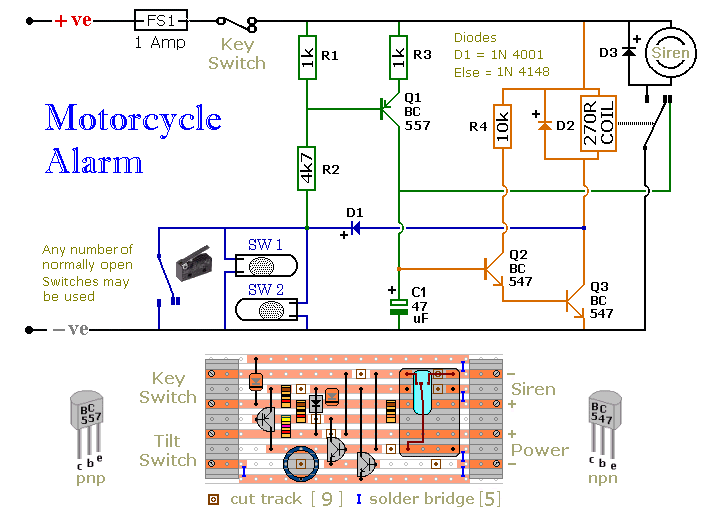
The circuit board and switches must be protected from the elements. Dampness or condensation will cause malfunction. Without its terminal blocks, the board is small. Ideally, you should try to find a siren with enough spare space inside to...
There are digital and analog methods that can be used to compensate for the nonlinearity of a PT100 RTD. Digital linearization can be implemented through various techniques. Compensation for the nonlinearity of a PT100 RTD (Resistance Temperature Detector) is essential...
This week involved the completion of several objectives. Initially, software was downloaded to design the schematic for a circuit intended for translation onto a PCB. A significant portion of the week was dedicated to tutorials and familiarization with the...
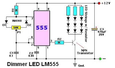
The LM555 timer IC can be utilized in various electronic projects, including the creation of an analog timer. According to the datasheet, the LM555 is versatile and can be adjusted to set timers based on specific requirements. The schematic...
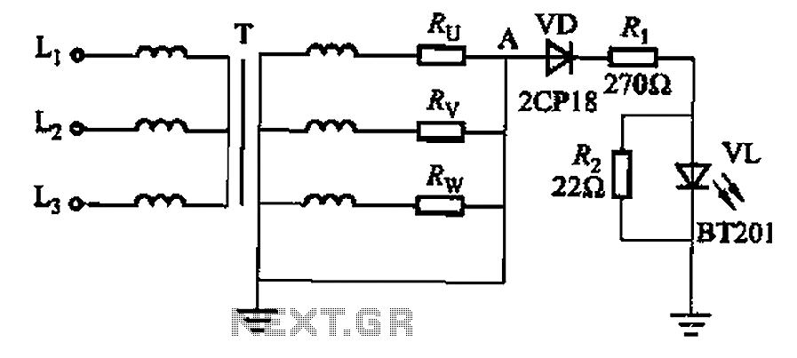
It is well understood that if the power transformer neutral line is disrupted, an unbalanced three-phase load can easily result in overvoltage conditions, potentially damaging electrical equipment such as household appliances and lamps. The neutral circuit alarm system is...
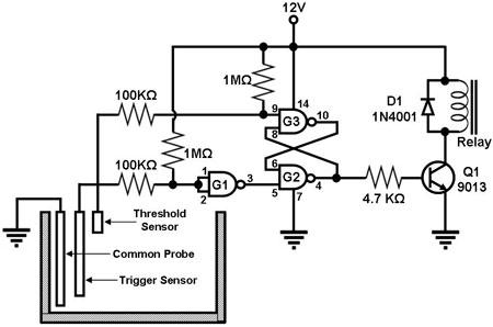
Figure 1 illustrates a circuit designed to monitor the water level in a tank and control a water pump accordingly. The primary component of the circuit is the CD-4011 Quad NAND gate, with three of its gates utilized as...