
PIC12F629 based IR decoder

The IR Widget circuit consists of several key components that work together to achieve effective infrared signal capture and processing. The main component is the PIC12F629 microcontroller, which serves as the heart of the system. This microcontroller is programmed to handle the timing and data processing tasks necessary for accurate signal analysis. The infrared detector module is connected to one of the microcontroller's input pins, allowing it to detect incoming infrared pulses. The module is sensitive enough to capture signals at close range, making it ideal for detailed analysis.
The microcontroller's firmware is designed to count the number of detected pulses within a defined 100-microsecond interval. This counting process is achieved through the use of timers and interrupts, allowing the microcontroller to operate efficiently without significant CPU load. The captured pulse count is then transmitted to a connected PC via a serial interface at a baud rate of 115200 bps. This high-speed communication ensures that data is relayed in real-time, enabling quick analysis and visualization.
The IR Widget's design also incorporates a power management feature, drawing power directly from the serial port. This eliminates the need for an external power supply, enhancing portability and ease of use. The use of standard asynchronous serial communication allows compatibility with a wide range of devices, including USB-to-serial converters, which are essential as traditional serial and parallel ports become less common.
For long-range applications, the IR Widget can be paired with an infrared demodulator module. This module is tuned to specific carrier frequencies, allowing it to filter out unwanted signals and focus on the desired infrared communication. The integration of this module into the IR Widget expands its functionality, making it suitable for various remote control applications.
The accompanying software provides a user-friendly interface for visualizing the captured infrared signals. The graphical representation allows users to observe the timing and duration of carrier on and off periods, as well as the pulse counts. This capability is invaluable for troubleshooting remote control systems or developing new infrared communication protocols.
In summary, the IR Widget represents a versatile and effective solution for capturing and analyzing infrared signals from remote controls. Its combination of a microcontroller, infrared detection modules, and software visualization tools makes it a powerful tool for both research and practical applications in the field of infrared communication.The IR Widget captures the infrared signals used by remote controls. It is able to determine the carrier frequency and demodulate the carrier in the digital or analog domain. The captured information can be used to reproduce or recognize the signal. The hardware is designed to be as simple and low cost as possible. A PIC12F629 was used for the pro totype, but almost any PIC that uses the 12 or 14 bit instruction set could be used. The usual approach to low cost IR capture typically consists of an IR detector or demodulator module connected to a serial or parallel port. This can work quite well when the CPU is dedicated to servicing the port. It does not work very well within a preemptive multitasking operating system. The OS is constantly servicing hardware interrupts even when the system is idle, so the IR capture is constantly interrupted.
CPU usage is high when polling is used. Using the hardware interrupt capability of the port can greatly reduce CPU load, but interrupt latency may cause inaccurate results. Parallel and serial ports are becoming less common, and USB adapters do not work for these simple circuits.
The IR Widget solves these problems by using a microcontroller to do precise timing and send the data to the PC using ordinary asynchronous serial transmission. This allows the OS to service the serial port with it ’s normal drivers and allows the use of USB to serial converters.
The circuit is powered from the serial port and the PIC directly drive the serial rx data line. An infrared detector module is used to allow the PIC to see every infrared pulse at close range. This allows for greatest detail and accuracy. An infrared demodulator module can also be used to allow for long range reception with less detail. Infrared remotes typically use a carrier frequency of 30 to 60 kHz. The carrier is keyed full on and full off. Carrier on times typically range from 400 microseconds to several milliseconds. Carrier off times typically range from 400 microseconds to more than 100 milliseconds. To measure the frequency of a pulsed carrier, a short gate time is required. An ordinary frequency counter with 1 second gate will not give an accurate reading. The frequency could be determined from the period of one cycle, but this would require a rather high resolution measurement for a precise reading. The IR Widget counts the number of infrared pulses that occur within a 100 microsecond period. The count is sent to the PC at 115200 bps. This repeats every 100 microseconds. To calculate the carrier frequency, the received data is scanned for the highest count. As long as there are pulses of 200 microseconds or greater duration, there will be samples from periods where the carrier was on for the entire sample period.
These periods will have the highest count or one less than the highest count. The sum of all these periods is used to calculate the carrier frequency with reasonable precision. Once the carrier frequency is know, the periods with lesser counts can be evaluated to determine the duration of the carrier during those periods. A Microsoft Windows program is used to transform the data gather from the IR Widget in to a graphical representation of the infrared signal.
The display is similar to an oscilloscope or logic analyzer. The time of each carrier on and off period is shown as well as the count of pulses during the carrier on periods. Each capture is also written to a text file. The infrared detector module for the previously described capture mode has a very short range. The remote must be within a few inches of the detector module. This is fine for research, but not suitable for remote control. Devices that are controlled by infrared remotes typically use an infrared demodulator modules. These modules are tuned to a specific carrier frequency and have a range of 20 feet or more. The IR Widget can accommodate such a module and has code for measuring the time 🔗 External reference
Related Circuits
The following circuit illustrates a Single Supply Phase Locked Loop Circuit Diagram. This circuit is based on the LM331 integrated circuit. Features include the response of... The Single Supply Phase Locked Loop (PLL) circuit utilizing the LM331 integrated circuit is...
The circuit automatically lights a bulb upon the arrival of a telephone ring and simultaneously mutes the audio from the music system or TV while the telephone handset is off-hook. The lighting of the bulb not only indicates an...
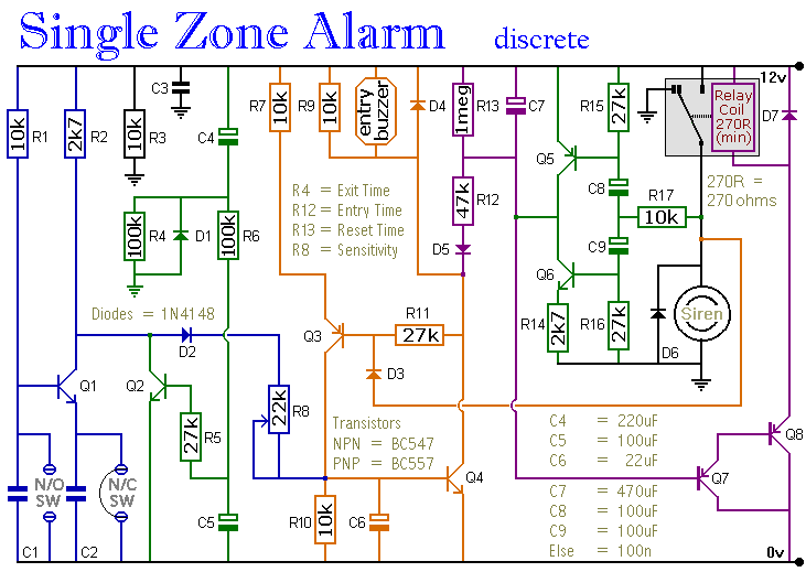
The circuit incorporates automatic exit and entry delays, a timed bell cut-off, and a system reset feature. It accommodates both normally-open and normally-closed switches and is compatible with standard input devices such as pressure mats, magnetic reed contacts, foil...
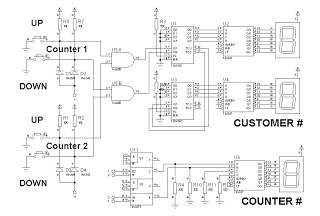
This is a simplified design utilizing an up/down counter integrated circuit (IC), specifically the 74192. This versatile logic IC features separate pins for counting both up and down. Additionally, an RS latch is incorporated to indicate the current counter...
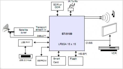
The STI5211 is a standard definition, full back-end processor designed for satellite set-top boxes, adhering to ATSC, SMPTE VC-1, DVB-S2, DIRECTV, DCII, and ARIB BS4 specifications. It delivers high performance for low-cost standard definition systems. Compared to the STi5202,...
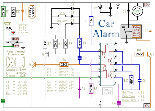
This car alarm circuit includes Exit and Entry delays, an instant alarm zone, an intermittent siren output, and an automatic reset function. By incorporating external relays, it is possible to immobilize the vehicle and activate the lights. The car alarm...