
logic based digital queuing
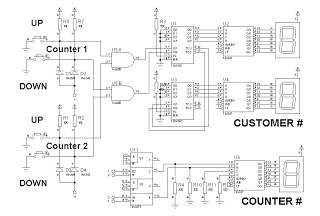
The 74192 up/down counter is a synchronous binary counter that can count in both directions, providing flexibility in counting applications. It operates on a clock signal and can be controlled using up and down control pins. The counter can be reset to zero or preset to a specific value, depending on the configuration of the control inputs.
In this design, the RS latch serves as a memory element that holds the current state of the counter output. The RS latch is triggered by the output of the 74192, ensuring that the displayed counter number is stable and does not fluctuate with the clock signal. This aspect is crucial for applications where a reliable indication of the count is necessary.
The circuit may also include additional components such as resistors and capacitors for debouncing the control signals and stabilizing the power supply. Proper power management and decoupling techniques should be employed to ensure the reliable operation of the IC, especially in environments with electrical noise.
Overall, this simplified design effectively demonstrates the functionality of the 74192 up/down counter and the integration of an RS latch for output indication, making it suitable for various counting applications in digital electronics.This is a simplified design using a up/down counter IC, 74192. It is a versatile logic IC that has a separate pins for up and down count. Also, an RS latch is used for the indicator of the counter number. 🔗 External reference
Related Circuits
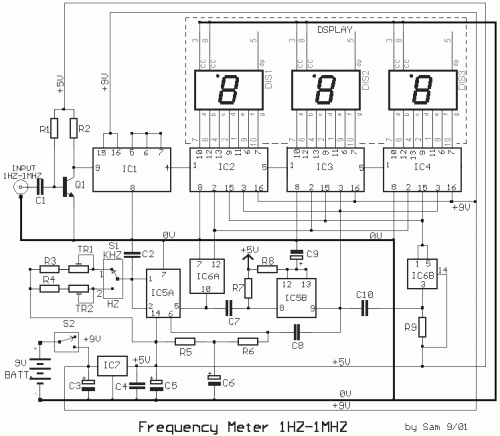
The circuit was designed to create a low-cost frequency meter that will cover the range of 1 Hz to 1 MHz with a digital indication using three 7-segment displays. The frequency meter circuit operates by measuring the frequency of an...
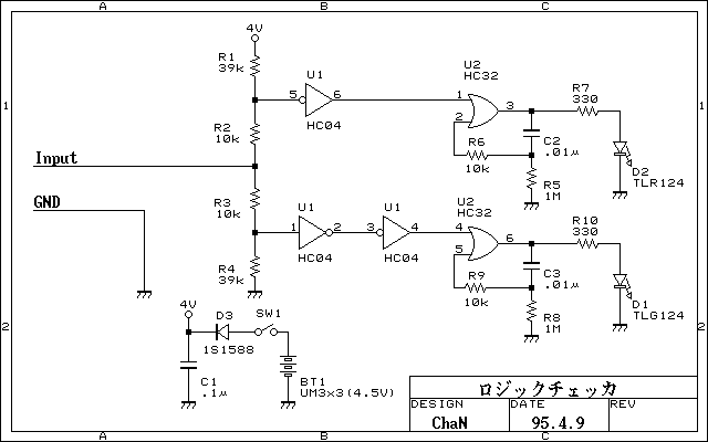
Simplified logic checker. Logic voltage levels have the ability to display LED. "H" in the LED is green, "L" and red LED lights, and so both the open and goes out. But not only that was put on the...
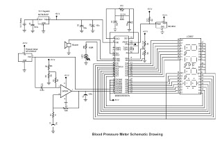
This digital circuit outlines a concept for a digital blood pressure meter that incorporates an integrated pressure sensor, analog signal conditioning circuitry, microcontroller hardware/software, and a liquid crystal display. The sensing system measures cuff pressure (CP) and extracts pulses...
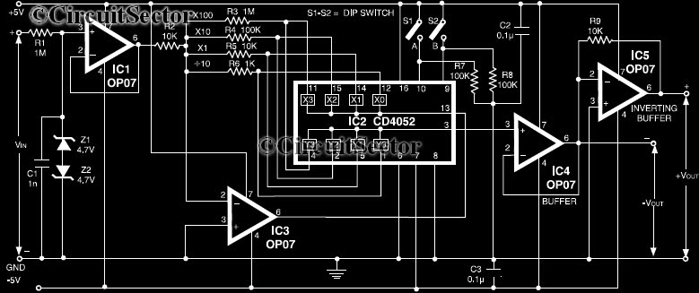
This circuit is a precision amplifier with digital control, designed for signal conditioning of low-output transducers operating in the millivolt range. The resistors R3 to R6 can be user-selected, with values ranging from 1 kilo-ohm to 1 mega-ohm, allowing...
A simple blocking oscillator circuit can be utilized to increase voltage by leveraging the properties of coil inductance (V = L di/dt). Such a circuit is illustrated in Figure 1. The blocking oscillator circuit is a type of oscillator that...
A logic pen, also known as a logic detection probe, is a commonly used tool for detecting the logic state at various points within digital circuits. The logic states in digital circuits are typically categorized into three types: a...
Warning: include(partials/cookie-banner.php): Failed to open stream: Permission denied in /var/www/html/nextgr/view-circuit.php on line 713
Warning: include(): Failed opening 'partials/cookie-banner.php' for inclusion (include_path='.:/usr/share/php') in /var/www/html/nextgr/view-circuit.php on line 713