
pic16f877 timer0 code and proteus simulation

The PIC16F877 microcontroller is a versatile device widely used in embedded systems. Timer0 is an essential peripheral that provides timing and counting capabilities, which can be utilized for various applications such as generating time delays, event counting, and pulse width modulation.
To configure Timer0, the relevant registers must be set appropriately. The T0CON register controls the operation of Timer0, allowing the selection of the timer mode (16-bit or 8-bit), the prescaler settings, and the clock source. The prescaler can be configured to divide the input clock frequency, which effectively extends the timer's counting range.
Interrupt handling is a critical aspect of using Timer0. The Timer0 interrupt flag (T0IF) is set when the timer overflows, which can be monitored to trigger an interrupt service routine (ISR). To enable Timer0 interrupts, the T0IE bit in the PIE1 register must be set, and the global interrupt enable (GIE) bit must also be activated.
In practice, the implementation involves initializing Timer0, enabling the appropriate interrupts, and writing the ISR to handle the overflow condition. The ISR can perform tasks such as toggling an LED, updating a counter, or executing other time-sensitive operations.
Overall, this tutorial serves as a comprehensive guide for users looking to effectively utilize Timer0 in the PIC16F877 microcontroller, providing insights into both configuration and interrupt management.This PIC16F877 microcontroller tutorial answers the question, "" How to use timer0 of PIC16F877 and how to handle its interrupts? "" Using PIC16 simulator (P.. 🔗 External reference
Related Circuits
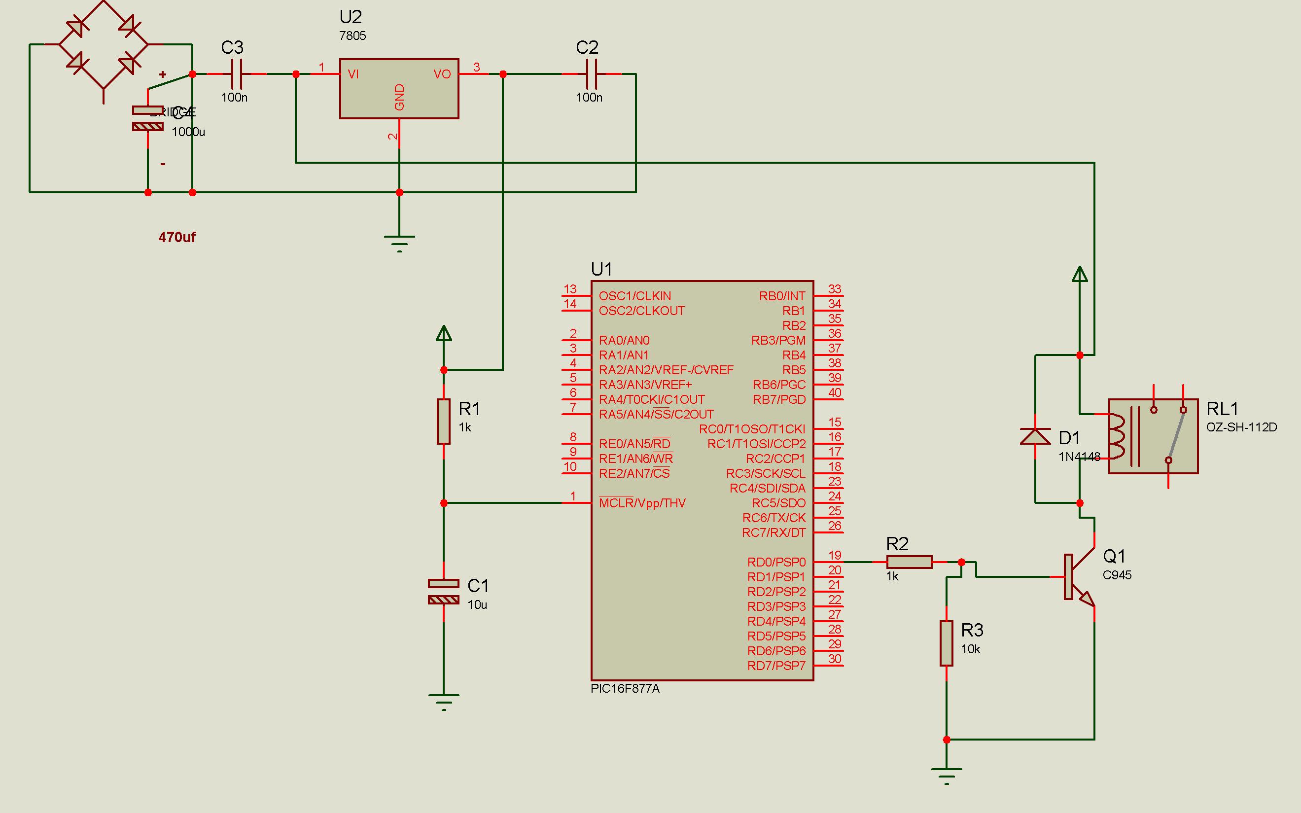
Connect a relay with a PIC microcontroller, and whenever a load is applied to the relay contacts, the PIC16F877A resets. This issue has been partially resolved by triggering another relay from the basic relay attached to the PIC, but...
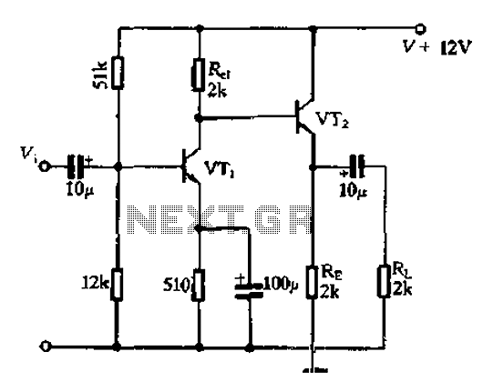
Available RC coupling between its two stages can also be directly coupled. This is in addition to the common-emitter total radio circuit configuration, which is widely used. Outside the previously described common-emitter circuit, a total group or common-emitter circuit...
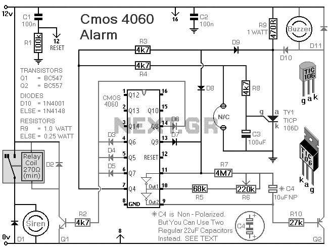
The Supertex HV440 is utilized for creating a pulse width modulated high voltage ring generator in telecommunication applications. The HV440 can function in both closed-loop and open-loop configurations. A closed-loop design, while more intricate, offers improved load regulation and...
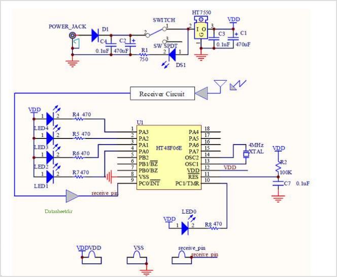
This is a simplified version of the Universal Keypad-Operated Switch. The design has been modified to reduce circuit complexity and the number of components required, resulting in somewhat less secure code functionality. However, it remains adequate for many applications....

The DTMF decoder can be powered by a 9V battery or through a parallel printer port. It is capable of detecting and displaying all 16 DTMF digits on a computer screen in real-time. The accompanying Windows program can run...

The circuit is designed to fit snugly, eliminating the need for adhesive. It is recommended to test the fit multiple times, making incremental adjustments until a snug but movable fit is achieved. The entire circuit should be placed inside...