
How To Build A Simple Code-Operated Switch

The Universal Keypad-Operated Switch circuit is designed for versatility and ease of use, making it suitable for various applications that require controlled access. The circuit's operation is governed by the keypad input, which allows user-defined access codes. The relay acts as the main switching element, controlling the load based on the code entered.
The choice of relay is critical, as it determines the voltage and current handling capabilities of the circuit. For low-voltage applications, an SPCO/SPDT relay can suffice, while high-power applications may require multi-pole relays to manage multiple loads or provide additional functionality. The recommendation to avoid switching mains voltage with the on-board relay emphasizes the need for safety and proper isolation.
The code entry process is straightforward: upon power-up, the relay remains energized, allowing the user to enter a predetermined code using the designated keys. The connection of other keys to terminal "E" provides a method for the user to reset or re-energize the relay without needing to re-enter the code. The inclusion of a BC547 transistor allows for flexibility in operation, catering to different user preferences regarding the relay's initial state.
The circuit's design includes fail-safes, such as the detection of incorrect key presses, which prevents unauthorized access attempts. This feature enhances security by ensuring that only the correct sequence of key presses will activate the relay. The requirement for a keypad with a common terminal and separate connections for each key ensures compatibility and reliability in operation.
In summary, the Universal Keypad-Operated Switch circuit is a practical solution for applications requiring controlled access, with considerations for safety, security, and user flexibility. The accompanying support materials provide comprehensive guidance for successful implementation and customization of the circuit.This is a simplified version of the Universal Keypad-Operated Switch. I have modified the design to reduce the complexity of the circuit - and the number of components required. As a result - the code is somewhat less secure. However, there should be lots of situations where it will still be adequate. The circuit is drawn with a 12-volt supply - but it will work at anything from 5 to 15-volts. All you have to do is choose a relay suitable for the supply voltage you want to use. Replace the SPCO/SPDT relay with a multi-pole relay - if it suits your application. Do not use the "on-board" relay to switch mains voltage. The board`s layout does not offer sufficient isolation between the relay contacts and the low-voltage components. If you want to switch mains voltage - mount a suitably rated relay somewhere safe - Away From The Board.
Choose the four keys you want to use as your Code - and connect them to "A B C & D". Wire the common to R1 and all the remaining keys to "E". The circuit will power-up with the relay energized. To de-energize it - you must enter your code. To re-energize it - press any of the keys connected to "E". To reverse the operation of the circuit replace Q2 with a BC547. With an NPN transistor in this position - the circuit will power-up with the relay de-energized. To energize it - you must enter your code. To de-energize it again - press any of the keys connected to "E". Any keys not wired to "A B C & D" are connected to the base of Q1. Whenever one of these "Wrong" keys is pressed - Q1 takes pin 1 low and the code entry sequence fails. If you make a mistake while entering the code - simply start again. The Keypad must be the kind with a common terminal and a separate connection for each key. On a 12-key pad, look for 13 terminals. The matrix type with 7 or 8 terminals will NOT do. A 12-key pad has eight "Wrong" keys connected to "E". If you need a more secure code - use a bigger keypad with more "Wrong" keys. The Support Material for this circuit includes a step-by-step guide to the construction of the circuit board, a parts list, a detailed circuit description and more.
🔗 External reference
Related Circuits
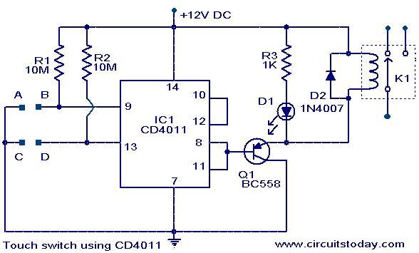
The following circuit illustrates a Touch Switch Circuit Diagram. This circuit is based on the CD4011 IC. Features include R1 and R2, which are the logic gates of the circuit. The Touch Switch Circuit utilizes the CD4011 integrated circuit, which...
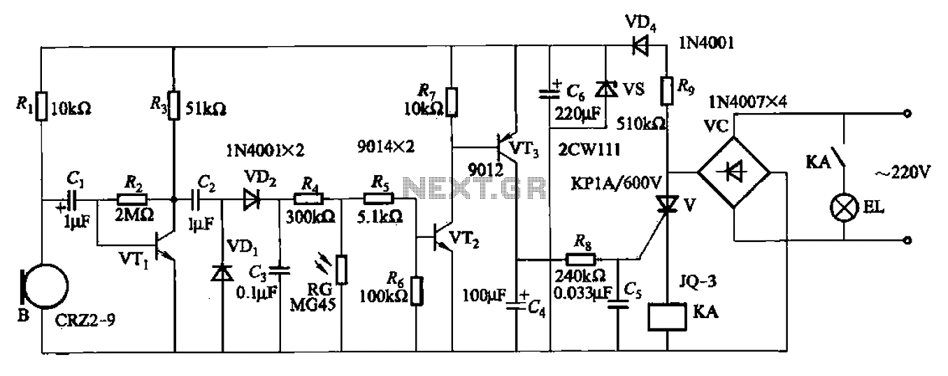
A resistor R8, capacitors Cd, and a thyristor V AC switch form a delay circuit. The lamp's lighting delay time is determined by the resistor Rs and capacitor C4, with a delay of approximately 40 seconds as indicated in...
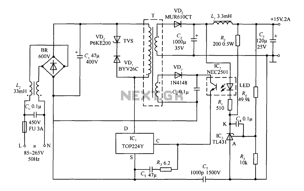
This circuit comprises a 15V TOP224Y, 2A output DC switching power supply. It utilizes three integrated circuits: IC1 is a monolithic regulator (TOP224Y), IC2 is an optocoupler (NEC2501), and IC3 is a precision voltage reference (TL431). The TL431 (IC3)...
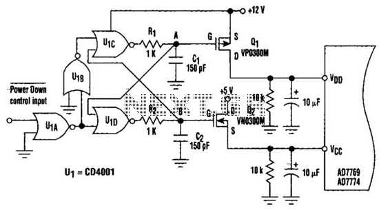
This circuit adds a power-down function to analog I/O ports, such as the AD7769 and AD7774. Additionally, the diodes typically required to protect the devices against power-supply mis-sequencing can be eliminated. In this design, MOSFETs Q1 and Q2 switch...
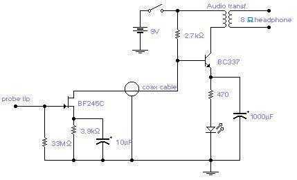
The circuit will come handy when you have to follow the mains wires buried in the wall or even water pipes provided they are not too far away (2-4cm max). It will also detect a conversation on a telephone...
One of the simplest methods of metal detecting is through a beat frequency oscillator. The circuit consists of two balanced oscillators: one provides a reference signal, while the other acts as the detector element. The frequency of the reference...