
Pick
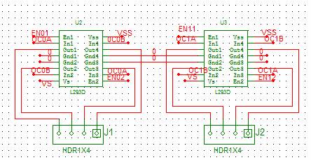
The Signal Distribution Board functions as a critical element in the 7400 pick system, facilitating the distribution of power and signals essential for the operation of stepper motors and sensor interfaces. The use of the L293D IC is particularly advantageous due to its dual H-bridge configuration, allowing for efficient control of the stepper motors. The choice of PWM control via the OC#A and OC#B pins enhances the system's performance by freeing the microcontroller from constant motor management, thereby enabling it to undertake additional processing tasks.
The ATmega8 microcontroller's limitation of three PWM pins necessitates consideration of alternative microcontrollers, such as the ATtiny2313 or ATmega16, which provide the required four PWM channels for optimal motor control. The sensor array for paper size detection is a pivotal feature of the pick system, allowing for accurate monitoring of paper levels and sizes. The interfacing of this sensor is straightforward, and the defined signal values provide a clear framework for understanding the operational status of the paper tray.
The initial version of the pick control program serves as a foundational tool for testing and validating the functions of the pick system. It is essential to maintain this version for reference as newer iterations are developed, ensuring that the core functionalities remain intact and operational. This structured approach to the development and testing of the pick control program will contribute to the overall reliability and efficiency of the 7400 pick system.The second is a Signal Distribution Board that relays voltage, ground, and other signals throughout the pick. We can use this board, and it is modeled on its page: Signal Distribution Board. The 7400 pick system has two stepper motors, both with two coils. To control these, we will need two H-Bridges per motor, or a total of four H-bridges. The L 293D IC has two H-Bridges on it, and appears to be capable; Josh and I (Jeff) have already been driving the one motor on the 7300 pick system with it. The OC#A and OC#B are PWM pins. We do not absolutely need to use PWM to drive the stepper motors, but it does free up the microcontroller to do other things as opposed to babysitting the motors.
The ATmega8 only has three PWM pins, and is therefore not adequate to drive the 7400 pick. The other two easy options with 4 PWM channels are the ATtiny2313 or the ATmega16 The pick system has a sensor for detecting the paper size that is basically an array of switches. For the 3 different sizes, SRA3, 11 x 17, and 8 1/2 x 11, below is a simple diagram of how the sensor should be interfaced to.
Also below is a table that shows what the signal values will be for the three sizes. Note that the IC checking the lines 0 3 has internal pull-ups: so if switch 3 is closed on the sensor, it is pulled low. 000 - Paper tray has reached paper pick height and paper is half full 001 - Paper has reached paper pick height and there is no paper 010 - Paper tray has almost reached paper pick height 011 - Paper tray lower than paper pick height 100 - Paper tray is full (filled to the top) and has reached paper pick height 110 - Paper tray is full (filled to the top) and is not at paper pick height 111 - Paper tray not yet raised and is half full Taking the information regarding paper size, learning how the sensors on the pick system, and understanding how to control a 4 wire stepper motor brings us to our first version of a pick control program: Pick Control C file (dated 2/21/2007) Note that this version should NOT be overwritten by newer versions!
This is more of a test program that makes every needed function on the pick operate correctly, but not with the netburner. Newer versions should appear on this page below. 🔗 External reference
Related Circuits
The LA1061M is an antenna switching controller designed for mobile radio equipment. It utilizes several inputs from the receiver circuitry to choose between the main antenna and a sub-antenna based on signal strength and quality. Weak and strong signals...
Although several variations of a standard RIAA preamplifier for magnetic phono cartridges have been published, there has not yet been a preamp stage designed specifically for ceramic cartridges. The RIAA preamplifier is an essential component in the audio signal chain,...
A schematic of a board featuring the PIC16F84 microcontroller, along with other compatible PIC microcontrollers that can be connected to the USB PICKit2 programmer. Additionally, there are concerns regarding the potential damage to the programmer when experimenting with oscillator...
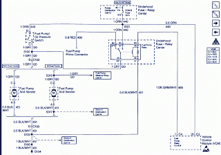
Pump prime connector, power distribution cell, fuel pump and sender, dual tanks, fuel pump balance relay, vehicle control module, underhood fuse relay, ECM fuse. The described components are integral to the operation and management of a fuel system in a...

The preamplifier circuit is designed to offer appropriate loading for phono cartridges with reluctance. It achieves a gain of approximately 25 dB at 1 kHz (converting an input of 2.2 mV to an output of 100 mV). The circuit...

A passive high-pass filter has been added after the output of the operational amplifier (op-amp) to eliminate DC offset, with the op-amp powered by +12V and the negative supply at 0V. A feedback resistor (Rf) of 500K Ohms is...