
1997 Chevy 2500 Pick Up 5 7l engin Wiring Diagram

The described components are integral to the operation and management of a fuel system in a vehicle, particularly in setups involving dual fuel tanks.
The pump prime connector is utilized to initiate the fuel pump, ensuring that fuel is delivered to the engine during startup. The power distribution cell serves as a central hub for electrical connections, distributing power to various components within the vehicle's electrical system, including the fuel pump and sender.
The fuel pump and sender work in tandem to deliver fuel from the tanks to the engine while providing feedback on fuel levels. In a dual-tank configuration, the fuel pump balance relay plays a crucial role in managing the operation of the pumps to ensure equal fuel distribution from both tanks, optimizing performance and efficiency.
The vehicle control module (VCM) is the brain of the vehicle's electronic systems, processing inputs from various sensors and controlling outputs to maintain optimal engine performance. The underhood fuse relay protects the electrical components by interrupting power in case of a fault, while the ECM fuse specifically safeguards the engine control module, ensuring its reliability and functionality.
This schematic would typically include connections between these components, showcasing the flow of power and data within the fuel management system. Proper placement and specification of each component are essential for ensuring system reliability and efficiency.pump prime connector, power distribution cell, fuel pump and sender, dual tanks, fuel pump balance relay, vahicle control module, underhood fuse relay, ECM fuse. 🔗 External reference
Related Circuits
A model has been constructed based on the principles of a horizontal steam engine, where the steam cylinder is substituted with an electromagnet featuring a moving core. The construction specifics are less significant, as the accompanying photos provide all...
The CD4001 quad 2-input NOR gate is a highly versatile integrated circuit (IC) that can be utilized in numerous applications. This example demonstrates its use in a simple alarm system. The recommended power supply voltage for the CD4001 ranges...
This digital DIY tachometer for bicycles utilizes two reed switches to gather speed information. The reed switches are positioned near the wheel rim, where permanent magnets, attached to the wheel spokes, pass by and activate the switches. The speed...
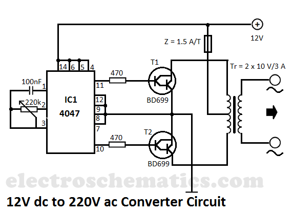
This DIY 12V to 220V voltage converter is built with the CMOS 4047, which serves as the main component of this compact voltage converter that transforms 12V DC into 220V AC. The 4047 is configured as an astable multivibrator,...
The external audio spectrum display circuit is designed for high-end audio equipment, providing both real-time playback signal analysis and visually appealing effects. This display does not require any electrical connections to the sound equipment; it can simply be placed...
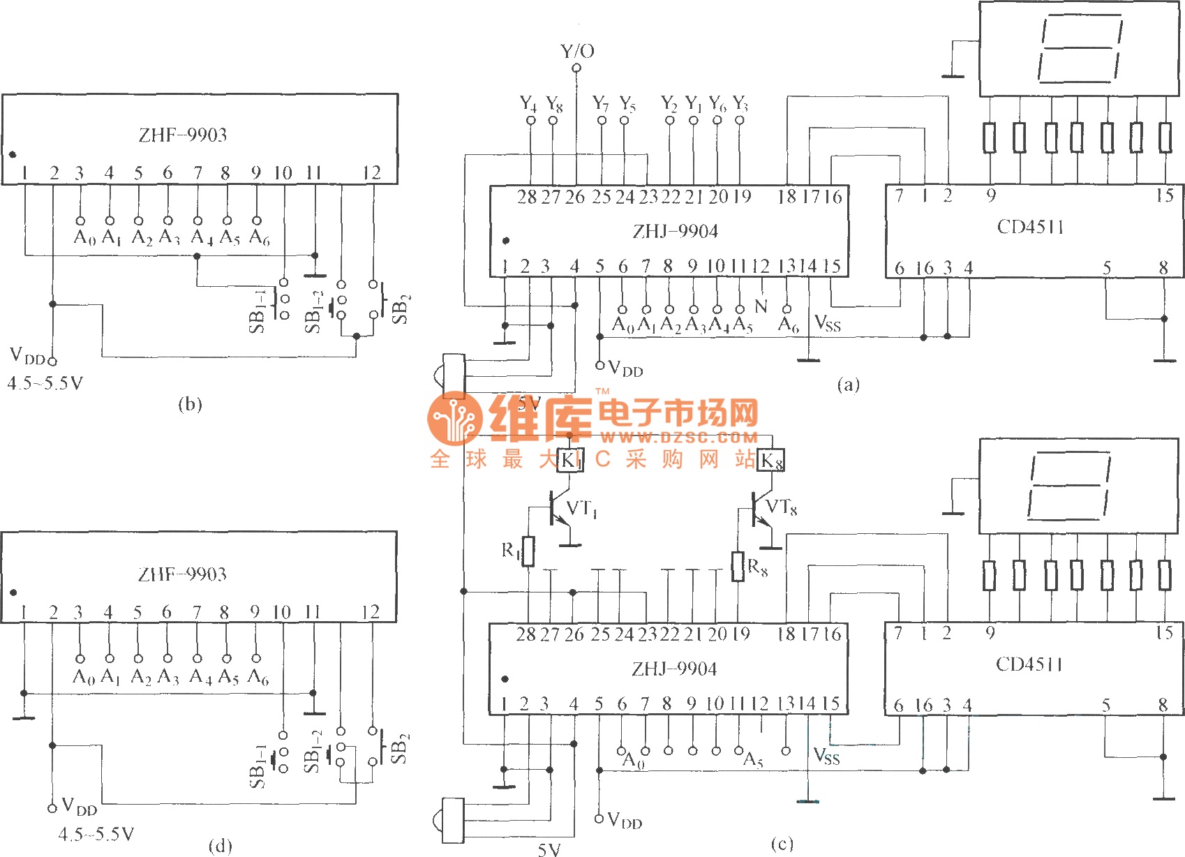
This is an eight-way signal remote control selection circuit composed of ZHJ-9904. It includes a remote control transmitter circuit, an eight-way switch control circuit, and a remote control transmitter. The eight-way signal remote control selection circuit utilizing the ZHJ-9904 is...