
PID PROJECT
The closed-loop temperature control system described features a comprehensive architecture integrating various electronic components and control strategies. The primary components include the microprocessor, which serves as the central processing unit, the thermistor for temperature sensing, and the incandescent light bulb as the actuator. The system operates by continuously monitoring the temperature via the thermistor, which is part of a bridge circuit that converts the temperature reading into a voltage signal. This signal is amplified by an instrumentation amplifier before being digitized by the A to D converter for processing by the microprocessor.
The control algorithm implemented in the microprocessor utilizes a proportional control strategy. The error signal, derived from the difference between the desired set point and the current temperature reading, is calculated and used to determine the necessary adjustments to the actuator. This adjustment is communicated through a D to A converter, which translates the digital control signal back into an analog signal to modulate the power supplied to the light bulb. The system's feedback loop ensures that any deviations from the set point are corrected by dynamically adjusting the power output to the lamp.
The user interface, developed in Visual Basic 6, provides an intuitive platform for setting the desired temperature and monitoring system performance. It displays real-time data, including the current temperature, set point, and power output, allowing for effective user interaction and system oversight. The graphical representation of temperature tracking against the set point offers valuable insights into system performance and stability.
In summary, this closed-loop temperature control system exemplifies the practical application of PID control principles, specifically focusing on proportional control. The integration of various electronic components, coupled with a user-friendly interface, facilitates efficient temperature management, making it suitable for a range of industrial and laboratory applications. Further enhancements, such as the implementation of integral and derivative control strategies and the addition of cooling mechanisms, could improve system performance and accuracy in maintaining the desired temperature set points.In order to manufacture large quantities of anything, there needs to be a manufacturing system or process in place. The manufacturing process can be open loop or closed-loop. In an open-loop system, variables are controlled manually. In a closed-loop system, variables are controlled automatically. The majority of applications in industry require a closed-loop system. The objective of a closed-loop system is to keep one or more controlled variables equal to the desired set point. The set point is where you would like the measurement to be. The thermostat in your house and the cruise control in your car are common examples of how controllers are used to automatically adjust some variable to hold the measurement at the set point.
The controlled variable is the actual variable being monitored and maintained. It is monitored by a measurement device that sends a feedback signal to the error detector. The error detector compares the feedback signal to the set point and creates an error signal that is sent to the controller. The controller determines what action to take in order to match the set point and then sends a signal to the actuator that physically adjusts the manipulated variable.
The manipulated variable is the energy that is altered by the actuator. The adjustment of the manipulated variable causes the controlled variable to change to the desired set point. There are many different types of closed-loop systems and they are generally defined by the kind of process or system they control.
In industry, PID controllers are common closed-loop controllers. PID stands for Proportional (Gain), Integral (Reset), and Derivative (Rate). The terms Gain, Reset, and Rate are functions that determine how fast the controller will change the output signal. Proportional control is the easiest feedback control to implement, and simple proportional control is probably the most common kind of control loop.
A proportional controller is just the error signal multiplied by a constant and fed out to the actuator. Integral control is used to add long-term precision to a control loop. It is almost always used in conjunction with proportional control. With derivative control, the controller output is proportional to the rate of change of the measurement or error.
The controller output is calculated by the rate of change of the measurement with time. Our project focuses on the most common control - Proportional Control. This type of control is also known as Gain control. The Controller uses the Error signal to decide how it will adjust the gain to the actuator. The Error signal is defined as the difference between set point and measurement. The EET 231 Closed-loop Temperature Controller was designed to keep a thermistor at a constant temperature using a microprocessor as the controller. It uses a GUI interface written in Visual Basic 6 to control the set point and view the output signal.
The actuator in this system is an incandescent light bulb. The heat from the light bulb is used to warm the thermistor. The set point is set in the Visual Basic program. The thermistor senses the temperature and the computer adjusts the current flow to the light bulb to maintain the set point value. The lamp is pulsed to change the thermistor value. The thermistor is part of a bridge circuit that is connected to an Instrumentation Amplifier that is connected to an Analog to Digital (A to D) converter.
Several combined electronic circuits were constructed and used in conjunction with the Visual Basic Program to complete the system. The next sections give a description of the entire system. The Visual Basic program used for this system controls the ports of the 8255 I/O chip within the microprocessor.
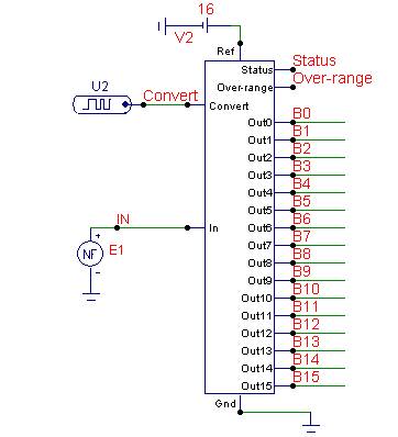
An 8086 interface board connects the microprocessor to the closed-loop control circuitry. This could be thought of as the starting point of the system. Once the computer decides how it will adjust the manipulated variable, the D to A converter is the first stop. Figure 1 shows a schematic of a D to A converter and Figure 2 shows the output signal. Once the saw tooth signal leaves the comparator it enters another D to A converter that outputs to an 8- Bit Counter.
Figure 1 shows a schematic of a 4-Bit counter. Current to the lamp is increased or decreased as the signal from the thermistor varies. The circuit that contains the thermistor is the bridge circuit. The thermistor is actually a leg of the bridge. The Visual Basic interface allows the user to adjust the set point. It also plots the temperature on a graph. The following screenshots show the Visual Basic interface during various conditions. In this screenshot, the set point is 74. The graph shows the output tracking the set point as the set point is adjusted. The Power To Lamp indicator shows the power being sent to the actuator at any given time. This system did a good job of tracking close to the set point, though the set point was never quite reached. The ambient temperature of the room caused a disturbance that made it hard for the output to reach the set point.
The addition of Integral and Derivative controls would solve this issue. Another possible improvement would be to add a cooling fan to the system. The lamp in the circuit could not cool down fast enough during broad set point changes. A cooling fan could be added to the system to improve the set point range precision. Overall, the closed-loop temperature controller is a good representation of the P` in PID. 🔗 External reference
Related Circuits
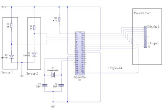
The dual-channel thermometer is a simple project based on a PIC microcontroller with ADC capabilities. It is an inexpensive thermometer that utilizes low-cost components and does not require high-sensitivity or expensive sensors. Instead, it employs a simple silicon diode...
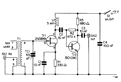
This simple aerial booster circuit design could serve as an alternative or a hobby project for creating an aerial booster device for Citizen Band (CB) radio. The aerial booster circuit is designed to enhance the performance of Citizen Band (CB)...
The classic Rangemaster is considered a source of some of the finest tones in rock guitar, from Clapton's Beano sound to Brian May's singing sustain tones. Although the effect is a simple one-transistor booster, finding a high-quality germanium transistor...
This simple telephone switching system is designed by Dr. Mustafa Kemal Peker for training purposes. All responsibility belongs to the user. Schematic and circuit details are included. The telephone switching system designed for training purposes serves as an educational tool...
TL072 is a low-noise JFET input operational amplifier characterized by features such as a common-mode input voltage range, high slew rate, operation without latch-up, compensated internal frequency, high input impedance at the JFET input stage, low noise, low total...
This audio noise filter circuit is a bandpass filter designed for the audio frequency range. It effectively filters out unwanted signals that fall outside the audio frequencies. The circuit consists of two filters: a low-pass filter and a high-pass...