
Guitar Stompbox & Effects Projects

The Rangemaster circuit, known for its distinctive tonal qualities, primarily consists of a single transistor amplifier, typically a germanium type in its original form. However, modern adaptations utilize NPN silicon transistors to enhance reliability and availability. The circuit operates by amplifying the guitar signal, boosting its level to drive the input of a tube amplifier into overdrive, producing a warm and rich distortion characteristic of classic rock tones. The Muffer circuit serves as an effective alternative, allowing for adjustments in component values to tailor the frequency response and gain characteristics, thus emulating the Rangemaster’s tonal qualities while mitigating the temperature-related drift associated with germanium transistors.
The Fuzzface circuit, a staple in electric guitar effects, employs a straightforward two-transistor configuration that produces a heavily distorted sound. The choice of transistors, whether germanium or silicon, influences the tonal output, with silicon transistors providing greater stability and consistency. The design allows for easy modification, enabling builders to experiment with different capacitors and resistors to achieve desired sonic characteristics. The inclusion of bypass switches and pot configurations facilitates user control over the effect, making it versatile for various playing styles. Overall, these circuits exemplify the intersection of simplicity and musicality, offering musicians a pathway to explore and enhance their sound.The classic Rangemaster is thought to have been the source of some of the best tones in rock guitar, from Clapton`s Beano sound to some of Brian May`s singing sustain tones. While the effect is a simple one-transistor booster, locating a good quality germanium transistor to use in building a clone of the Rangemaster can be a problem.
Furthermore, germanium transistors will drift in bias and gain as the temperature of the transistor changes. If we use the basic Muffer circuit and tweak the values of a few of the components we can produce a simple booster that has a lot of the character of the Rangemaster while being more stable and built from easy to find parts. This booster is best used to overdrive the input of a tube amp or otherwise create a bright boosted response.
The gain of the Muffer circuit has been reduced and input capacitor made smaller to create the proper frequency response. The Muffmaster can be made using the Muffer pc board layout shown above with the pads for D1, D2 and C3 left empty, or it can be built on the AMZ Multi-Purpose PCB.
The transistor can be almost any NPN silicon device and the same devices listed for the Muffer may be used. The current draw is low and therefore the battery should last a long time. Because the response of silicon transistors to overload is different from that of germaniums, the sound will not be an exact duplicate of the classic effect but it is interesting and useful nonetheless.
This cheap booster provides a lot of bang for the bucks - try it out! The Fuzzface is a simple two transistor design that produces the classic sound of the `60s. The original version used germanium transistors but the manufacturer soon switched to silicon since they were more readily available and produced stable, repeatable results. The BC108 was used in my 1973 original circuit but 2N5088, 2N5089, 2N3904 or similar transistors may be used.
C1 and C2 are aluminum electrolytics and C3 may be mylar or similar. The Fuzz pot should be linear taper and the Volume audio taper. Quarter-watt carbon film or metal film resistors are acceptable. A dpdt bypass switch may be used as shown in the schematic of the project above. The two pots are mounted off the pc board and connected to it by short jumper wires. The ground should connect to the ground lug on either the input or output jack. The input is shown as a stereo jack since by connecting the battery negative to the ring connection, the effect may be switched on when a plug is inserted into the jack. A standard mono plug will ground the ring connection and make the circuit from the battery negative to ground to power up the device.
I took a basic Fuzzface-type circuit and modified the component values so that a mosfet transistor could be used for Q2. The result was a high gain over-the-top distortion. I used a Radio Shack 2N3904 (hfe=233) for Q1 but a silicon transistor with less gain might sound better.
The input capacitor C1 has a lot of effect on the sound. When I had it as 0. 1uF the sound was a little on the dark side, and 0. 01uF was too thin for my Strat. Experiment with the value of the capacitor to find one that works with your instrument and amp. Use an audio taper pot for the volume and a linear taper for the Fuzz control. This project can be built on the same pcb as the Fuzzface shown above. The mosfet would be dropped in with its d-g-s leads going to the c-b-e pads respectively. Check out this interesting variation of the frequently used two-transistor distortion. I decided to update and simplify some of the aspects of this popular distortion circuit that I had developed with Aron Nelson. Complete schematic and pcb layouts are provided. Check out the complete article on the smooth-sounding Shaka 5 Overdrive. I was looking through some patents related to solid-state emulation of the tube sound, and found the US Patent No.
5, 032, 796, which had been assigned to St. Louis Music. I woul 🔗 External reference
Related Circuits
The issue began when a girlfriend expressed her frustration with mosquitoes disrupting her nights. It was recognized that mosquito sprays provide only temporary relief, as the insects tend to return after some time. A suggestion was made for an...
A collection of guitar fuzz, preamp, and operational amplifier (op-amp) electronic circuits and schematics designed for various guitar effects and distortion effects. This compilation includes a diverse range of electronic circuits that cater to guitarists seeking to enhance their sound...
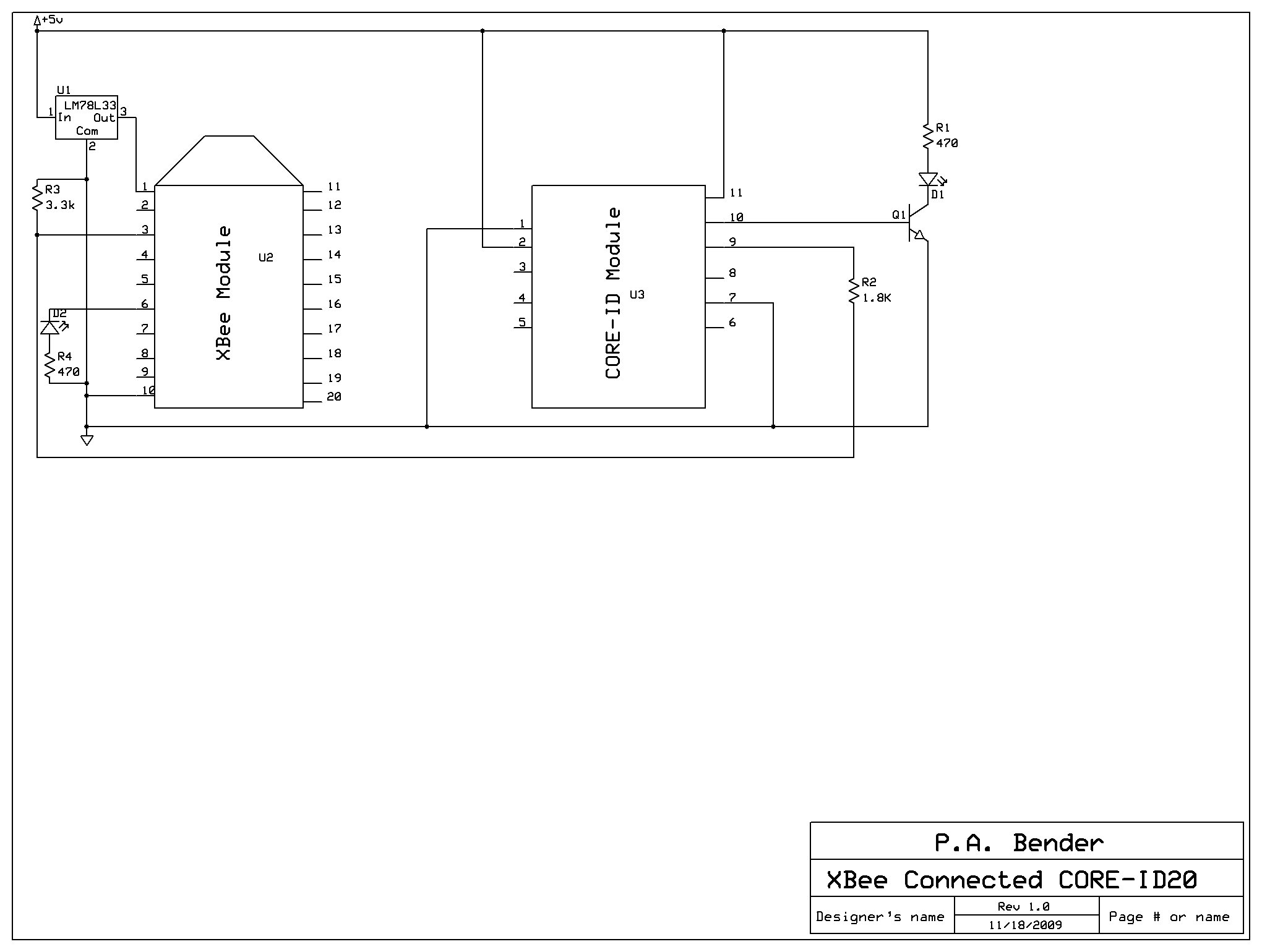
The remaining equipment is installed at the train layout's computer interface. The interface used is a Lenz LI100F configured to communicate at 9600 bps. Both the LI100F and the XBee Explorer Serial are set up as DCE (Data Communications...
The IRF820 MOSFET has a voltage rating of 500V; it should work well in preamp stages of most tube amps. The 100-ohm resistor is there to suppress H.F. oscillations. If the IRF820 is physically close to the 12AX7 plate,...

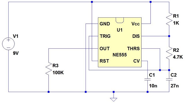
The tools used in this circuit are designed to create a noisy atmosphere. This circuit is relatively simple and is controlled by two 555 timer integrated circuits (ICs), assisted by other discrete components such as resistors and capacitors. The...
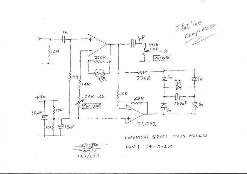
This circuit is a simple, low noise guitar compressor. The described circuit functions as a low-noise compressor specifically designed for guitar applications. It aims to reduce the dynamic range of the guitar signal, thereby allowing for a more consistent output...