
Pinball MAGNETISM circuits

The design and construction of the hand-held Gaussmeter involve several key components and considerations. The Hall effect device is the primary sensor, capable of detecting the presence and strength of a magnetic field. The choice of op-amps is crucial, as they amplify the small voltage signal generated by the Hall effect device, ensuring that even minor magnetic fields can be accurately measured. The voltage regulator ensures that the Hall effect device operates within its optimal voltage range, enhancing the accuracy of the readings.
The project case should be designed to allow easy access to the Hall effect sensor while providing protection for the internal components. The inclusion of filtering capacitors is essential for reducing noise in the signal, which can lead to inaccurate measurements. Calibration of the Gaussmeter is also an important step to ensure that the readings are accurate across the entire range of expected magnetic field strengths.
In practical applications, the hand-held Gaussmeter can be utilized not only in pinball machines but also in various fields where magnetic field strength and polarity are of interest, such as electronics, materials science, and even healthcare. The ability to easily measure and visualize magnetic fields can aid in troubleshooting and optimizing devices that rely on magnetic components. Overall, the design and functionality of the Gaussmeter exemplify the intersection of practical engineering and theoretical physics in the realm of magnetism.Had noticed balls getting stuck in the ball trough, not loading into an upkicker or not sitting directly on trough ball microswitches/optos, causing the machine to think a ball was missing. My first thoughts were that the ball trough itself had become pitted . I also doubted the angle of the ball trough for a moment, as a slight adjustment allowed the balls to roll down normally.
It then became apparent that the balls were magnetised and pulling together stronger than the force of gravity, or simply sticking to the metal ball trough. This did not happen for every game; only when certain balls landed in the trough next to other magnetised balls and also when they randomly lined up with magnetic polarity matching or opposing.
This would cause the pinballs to not line up with the microswitches in the ball trough, as they were pushing the top ball back up the trough by about a centimetre. A magnetic field can be represented by lines of induction or flux lines/dipoles. These lines are invisible and are produced by magnetized material or by electrical currents. Magnetic flux measured in Gauss (G) It is named after Carl Friedrich Gauss, an early researcher in the field of magnetism.
Magnetic objects are surrounded by a magnetic field. Some devices can detect this field and also give information about the direction/polarity of the field and even its strength. Show on magnetic flux paper/pole sensor foil gives a good visual indication of magnetised pinballs, although not very precise (see the picture & the video below).
Polarity indicator test magnet only indicates polarity on pinballs that are quite heavily magnetised, i. e. ~30 gauss. Electronic indication from a gaussmeter gives an electronic reading that equates to an actual magnetic force in Gauss.
Also indicates north & south polarity, which is difficult otherwise with a spherical pinball. Very precise although home made units may not be calibrated. Gaussmeters are used to measure the strength and polarity of a magnetic field. They use a electronic chip called a Hall effect device, which gives off a tiny electrical current when exposed to a magnetic field. The current is amplified with electronic circuitry and a meter shows the number of gauss (the units of magnetic field strength).
To find out how strong a magnet - or the strength of the magnetic field of a particular pinball - really is, you can purchase a Gaussmeter (also known as a magnetometer). These can be pretty difficult to find and relatively expensive, although they are precise and calibrated.
I built a hand-held Gaussmeter for measuring the polarity and strength of a magnetic field. It uses a Hall effect device and some op-amps from RS Components. I built two versions of these gaussmeters, each with different Hall effect ICs. The first was more sensitive than the other and the second one was designed to measure larger gauss readings. One Gaussmeter showed a difference in measured voltage of 7. 5 millivolts per gauss, with a range of 400 gauss. The other displayed a difference of 25 millivolts per gauss and is therefore more sensitive to smaller magnetic forces.
It was this version that I chose to use in a hand held gaussmeter To make a hand held pinball gaussmeter I built a variation of this circuit, due to the fact that the Hall effect IC I got from RS operates on an optimum voltage of over 8 volts, not 5 volts. So, a 7809, 9v voltage regulator was used. A more sensitive Hall effect IC was used, reading a deflection of 25 millivolts per gauss. (RS Components Hall effect sensor part number: SS94A1F ) and filtering capacitors were added to smooth the signals.
This unit to be powered by a 9V battery, housed in a small project case. The hall effect IC can then sit under a near-pinball sized hole in the case. This makes the unit easy to rotate the pinball to find optimum magnetism strength and polarity, whilst also being p 🔗 External reference
Related Circuits
Electrical signals travel along the neurons in the brain and body, continuously transmitting information throughout the complex system. Without these signals, the body would function like a plant, with different parts unaware of each other's conditions, making animal life...
This discussion covers three different Xenon flashing circuits from disposable cameras. From these circuits, unique techniques not found in any theoretical literature will be presented. The first circuit consists of six building blocks. An old disposable flash camera and...
Sur ce site, il est possible de trouver des contributions dans des domaines d'intérêt variés. Il est également possible de suivre l'auteur sur Twitter : @davbucci. Le site est constitué de contributions hétérogènes. L'accès se fait via les liens...
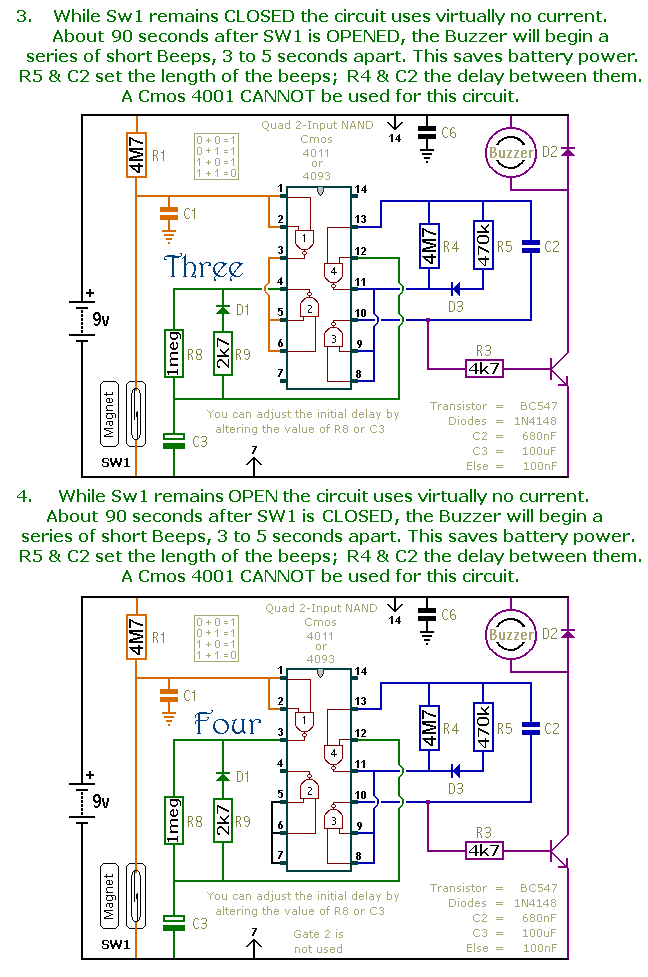
This is a collection of compact, self-sufficient alarm circuits designed for low standby current, making them ideal for battery operation. Some circuits are activated by normally-open and normally-closed switches, while others respond to variations in light or temperature. This...
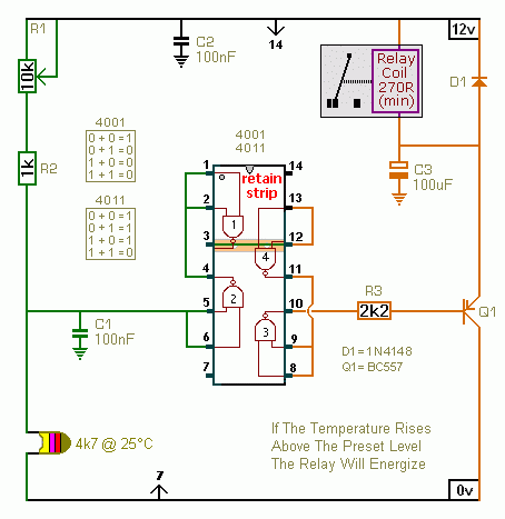
A CMOS 4001 or a CMOS 4011 can be utilized in this circuit, as both contain four two-input gates. The inputs of each gate are connected together, allowing them to function as simple inverters. This means that when both...
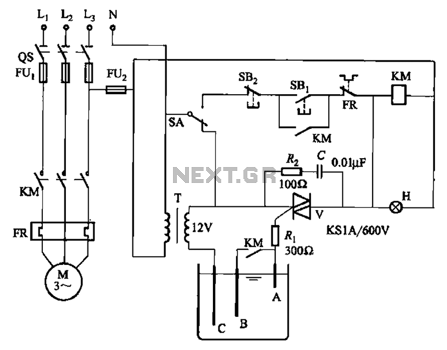
Bidirectional thyristor control manages the trigger voltage output from the step-down transformer at 12V when the water activates the electrodes. It is part of a drawable circuit that regulates the level. The circuit includes a current-limiting resistor (Ri) to...