
3 different Xenon flashing circuits
The Xenon flash circuits from disposable cameras serve as an excellent resource for exploring high-voltage applications in compact electronic systems. Each circuit is designed to efficiently generate a high-voltage pulse necessary for igniting the Xenon gas within the flash tube. The fundamental operation of these circuits typically involves a transformer, a capacitor, and a triggering mechanism.
The first circuit, comprised of six building blocks, can be broken down into the following components: a power source, a charging capacitor, a transformer, a switch, a flash tube, and a triggering circuit. The power source, typically a battery, supplies energy to charge the capacitor. The capacitor stores energy and releases it rapidly through the transformer, which steps up the voltage to the kilovolt range needed for the Xenon flash tube.
The modification process requires an old disposable camera, which houses the essential components, along with two additional parts that may include a resistor or diode to enhance circuit performance or modify the triggering mechanism. The implementation of these modifications can lead to improved efficiency, reliability, or functionality of the flash circuit.
The second and third circuits may introduce variations in the design, such as different transformer configurations or alternative triggering methods, allowing for experimentation and learning. These circuits are not only practical for photography but also serve as educational tools for understanding high-voltage electronics and the principles of capacitive discharge.
In conclusion, the exploration of Xenon flashing circuits from disposable cameras offers valuable insights into high-voltage circuit design, with practical applications that extend beyond photography. The modifications and techniques learned through this discussion can be applied to various electronic projects, enhancing skills in circuit design and troubleshooting.This discussion covers 3 different Xenon flashing circuits from disposable cameras. From them, you will learn circuit tricks that have NEVER been shown in any theory book.The first circuit covers 6 BUILDING BLOCKS.You will need an old disposable Flash Camera plus two extra parts to carry out the modifications.. 🔗 External reference
Related Circuits
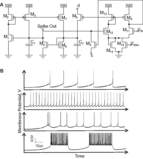
Hardware implementations of spiking neurons are highly beneficial for various applications, including high-speed modeling of large-scale neural systems, real-time operating systems, and bidirectional brain-machine interfaces. The specific circuit solutions for silicon neurons are dictated by the requirements of each...
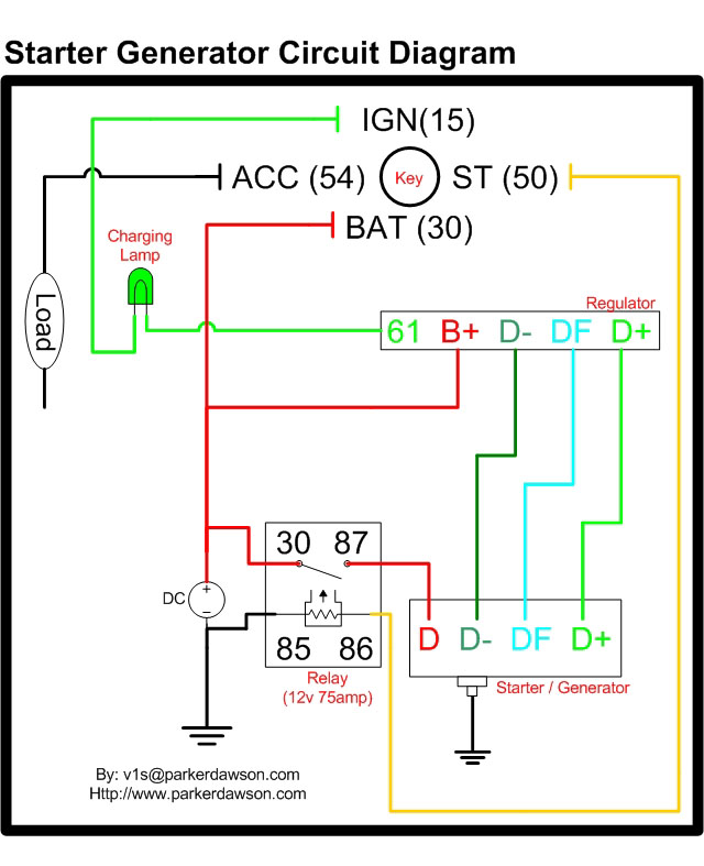
Circuit diagrams for both a Bosch and a Delco-Remy Starter-Generator are available, noting that the circuits differ. Due to a computer crash, the original diagrams and the associated email address were lost. However, in May 2004, both the email...
All electronic circuits were initially built on breadboards. Once the circuits were operational, they were soldered onto perfboards to create a more durable system. A power board was designed to stack two batteries in series, providing access to a...
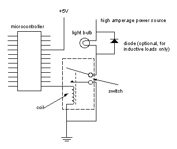
Digital output from a microcontroller is typically a low-amperage signal. For example, when a pin is set HIGH on the microcontroller (in Wiring/Arduino, it is digitalWrite(somePin, HIGH);), the voltage from that pin is usually +3.3V or +5V, with the...

Below 10 MHz, the development of engineering models is relatively straightforward and not significantly influenced by printed circuit board layout. In the VHF range, parasitic circuit elements and unwanted coupling can severely impact efforts to achieve cost-effective performance without...

The circuit described is a crystal oscillation circuit using a CM OS inverting configuration, designed to ensure accurate operation. It employs a BCD counter (IC2) capable of achieving a maximum oscillation frequency of 2 MHz, which is 100 times...
Warning: include(partials/cookie-banner.php): Failed to open stream: Permission denied in /var/www/html/nextgr/view-circuit.php on line 713
Warning: include(): Failed opening 'partials/cookie-banner.php' for inclusion (include_path='.:/usr/share/php') in /var/www/html/nextgr/view-circuit.php on line 713