
Plasma propulsion Lifter EM Antigravity

The concept of a spherical conductor maintaining a zero-volt potential is rooted in electrostatics, particularly in the behavior of conductors in electrostatic equilibrium. When a conductive sphere is charged, the charge distributes itself uniformly across the surface of the sphere. This results in the electric field inside the sphere being zero, which is a fundamental property of conductors.
In practical applications, when a coil-pack is introduced to this system, it can induce a voltage that may lead to the transfer of charge to the sphere. The coil-pack, often used in ignition systems or electromagnetic devices, generates a magnetic field when an electric current passes through it. This changing magnetic field can induce an electromotive force (EMF) in nearby conductive materials, including the sphere.
As the sphere continues to receive charge from the coil-pack, it can lead to various outcomes depending on the circuit design and the components involved. For instance, if the sphere is connected to a load, the continuous charging can result in a steady voltage output, which can be harnessed for powering devices. Alternatively, if the sphere is not properly managed, it may lead to issues such as dielectric breakdown or excessive current draw, which can damage circuit components.
To effectively integrate this concept into an electronic schematic, it is essential to include components such as the coil-pack, the conductive sphere, and any necessary load or regulation circuitry. The schematic should illustrate the connections between the coil-pack and the sphere, showing how the induced charge can be utilized or stored. Additionally, incorporating safety features such as voltage clamps or current limiting resistors would be prudent to prevent potential damage from overcharging or excessive current flow.
Overall, the interaction between the coil-pack and the conductive sphere presents a unique opportunity for energy transfer and storage in electronic applications, warranting careful consideration in circuit design and implementation.Originally Posted by Harvey The inside of a sphere is always zero volts potential, so it will keep taking new charge indefinitely from the coil-pack 🔗 External reference
Related Circuits
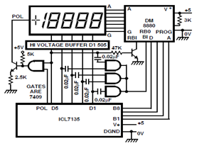
A circuit diagram for driving a plasma-type display using the ICL7135 is presented in the schematic. This application highlights the versatility of this integrated Analog to Digital Converter device. The ICL7135 is a high-precision, low-power, integrating Analog to Digital Converter...
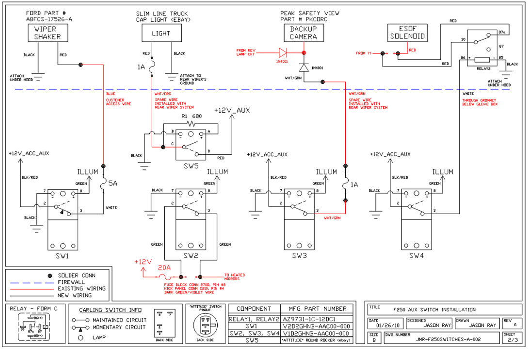
A +12V switched wire was routed back to the camera wiring and connected at the same point as the reverse lights. This configuration allows either the reverse lights or the switch to activate the camera. The critical component in...
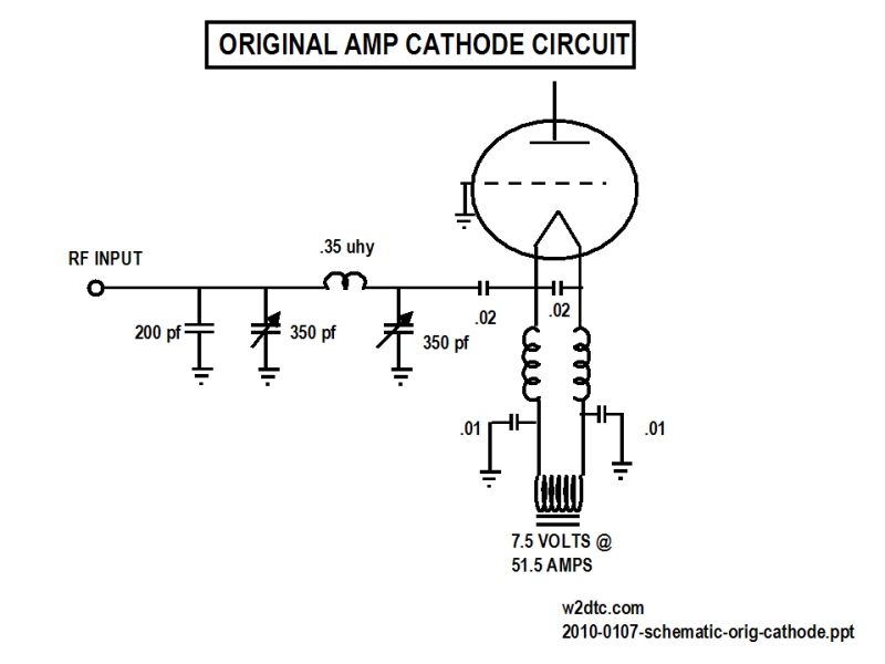
Conversion of a 3CX3000F7 plasma amplifier for use on the 40-meter band, including photographs and detailed descriptions. The 3CX3000F7 is a high-power vacuum tube typically used in RF amplification applications. Converting this amplifier for operation on the 40-meter band involves...
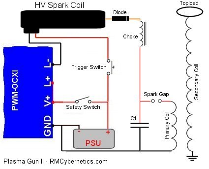
DIY Homemade Plasma Gun. This project demonstrates how to construct a functioning plasma gun. The plasma gun operates using a small Tesla coil. The DIY homemade plasma gun is an intriguing project that utilizes the principles of plasma generation through...
The issue is that the MOSFET is overheating due to the circuit utilizing a half-bridge configuration without a dedicated MOSFET driver. Alternatives to the TC4429 IC are sought to mitigate the overheating problem. It is noted that while power...
Plasma Globes were invented by Nikola Tesla before 1892. Glass-enclosed Tesla coil terminals containing low-pressure gases were part of his effort to develop a new lighting source not covered by Edison patents. The same device became an art object...