
Uplifter Switches

In this circuit configuration, a +12V switched wire is utilized to provide power to a camera system, which can be activated either by the vehicle's reverse lights or by a dedicated switch located on the dashboard. The connection point for the camera is strategically chosen to be the same as that of the reverse lights, ensuring that the camera can be powered in two different ways depending on the vehicle's operation.
The incorporation of diodes is essential in this design. Diodes are semiconductor devices that allow current to flow in one direction while blocking it in the opposite direction. In this application, they prevent the potential back-feed of voltage from one circuit to another, which could inadvertently activate the reverse lights when the camera is being accessed via the dashboard switch. Specifically, when the reverse lights are activated, the diode ensures that the voltage does not travel back to the switch circuit, thus maintaining the integrity of both control paths.
For implementation, the circuit can be designed as follows:
1. **Power Source:** A +12V supply from the vehicle's battery or ignition switch.
2. **Camera Wiring:** Connect the camera's power input to the point where the reverse lights are connected.
3. **Switch Control:** A toggle switch is installed on the dashboard, connected to the same input point as the reverse lights.
4. **Diode Placement:** Two diodes are employed—one diode connected from the reverse light circuit to the camera input, and another diode from the dashboard switch to the camera input. The cathode (the side with the line) of each diode should face towards the camera input to ensure proper current flow.
5. **Ground Connection:** Ensure that all components share a common ground to avoid potential ground loops or issues with circuit operation.
This design will provide flexibility in camera activation while ensuring that the circuits remain isolated, thus preventing any unintended behavior in the vehicle’s lighting system.Just ran a +12V switched wire back to the camera wiring and connected it to the same place that the reverse lights connect. That way, either the reverse lights or my switch can enable the camera. The important thing here is the use of diodes! These are used to isolate the two circuits, to keep the voltage from one of the "enable circuits" from back-feeding into the other.
For instance, without a diode, if I would turn the switch on the dash to see the camera, my reverse lights would come on. 🔗 External reference
Related Circuits
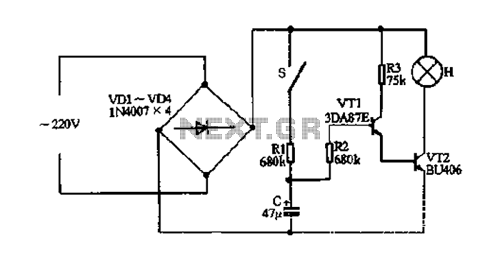
The fade circuit controls the lighting switch depicted in Figure 1-12. The figure illustrates the light switch S, H, which is responsible for lighting. Transistors VT1 and VT2, along with RC components, comprise the fade dimming control circuit. Given...
Touch operated switches are an attractive project for DIY electronics but they are not so common in commercial products. The reason for this is that, although there are many different ways of implementing a touch switch (leakage, hum pickup,...
The integrated circuit input side contains an oscillating circuit, where the oscillation frequency is determined by the external components L1, C1, and the sensor's equivalent capacitance. The equivalent capacitance increases as the sensor is immersed in liquid. The oscillating...
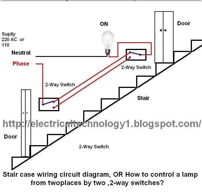
The circuit is complete, and the bulb is ON. To turn OFF the bulb from the upper switch at the top of the stairs, simply turn OFF the switch, which will break the circuit and turn the bulb OFF....
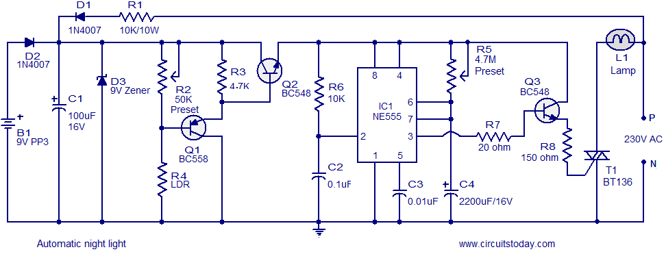
A simple and inexpensive automatic night light circuit designed using the timer IC NE555, which extinguishes after a preset time. This time can also be adjusted. The automatic night light circuit utilizes the NE555 timer IC configured in monostable mode....
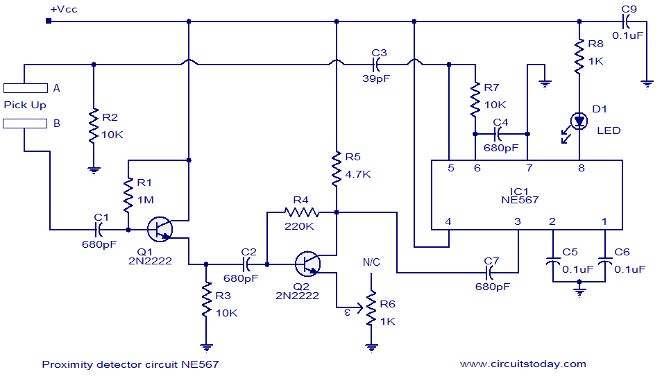
A simple proximity detector circuit utilizing the NE567 integrated circuit (IC). The circuit activates an LED when an object approaches the sensor. The NE567 is a versatile phase-locked loop (PLL) device commonly used for applications such as proximity detection due...