
Positive-regulator
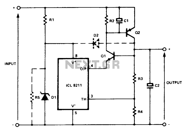
In the circuit, Q1 and Q2 are connected in the classic SCR or thyristor configuration. When higher input voltages or a minimal component count are required, the thyristor boost circuit can be utilized. The thyristor operates in a linear mode with its cathode serving as the control terminal and its gate functioning as the output terminal. This is referred to as the remote base configuration.
The circuit described employs two transistors, Q1 and Q2, arranged in a configuration that emulates the characteristics of a silicon-controlled rectifier (SCR). In this setup, Q1 and Q2 work together to control the flow of current through the circuit, allowing for efficient switching and amplification of the input signal. The thyristor boost configuration is particularly advantageous for applications requiring higher input voltages while maintaining a low component count, thus enhancing circuit efficiency and reducing overall size.
In this arrangement, the thyristor operates in a linear mode, where the cathode acts as the control terminal. This means that the voltage applied to the cathode influences the conduction state of the thyristor, allowing for precise control over the output. The gate serves as the output terminal, providing the necessary signal to drive the load connected to the circuit.
The remote base configuration allows for the control of the thyristor from a distance, which can be beneficial in applications where space constraints or layout considerations make direct control impractical. This configuration also offers improved stability and performance in various operating conditions, making it suitable for a wide range of electronic applications.
Overall, the combination of Q1 and Q2 in a thyristor boost configuration provides an effective solution for managing high-voltage signals while minimizing the number of components required, thus optimizing both the design and functionality of the circuit.In the circuit, Ql and Q2 are connected in the classic SCR or thyristor configuration. Where higher input voltages or minimum component count are required, the circuit for thyristor boost can be used. The thyristor is running in a linear mode with its cathode as the control terminal and its gate as the output terminal.
This is known as the remote base configuration. 🔗 External reference
Related Circuits
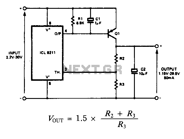
The IC8211 serves as the voltage reference and regulator amplifier, with Q1 functioning as the series pass transistor. Resistor R1 defines the output current of the IC8211, while capacitors C1 and C2 ensure loop stability and help suppress the...