
Power Audio Amplifier based on STK400xx
The power audio amplifier circuit utilizing the STK400xx series is designed to deliver high-fidelity sound output while remaining budget-friendly. The STK400xx series integrates several functions into a single package, which simplifies the design process and reduces the number of external components required. Typically, the circuit consists of the STK power amplifier IC, a few passive components such as resistors and capacitors, and a heat sink to manage thermal dissipation.
To construct this amplifier circuit, the following key components are necessary:
1. **STK400xx Amplifier IC**: This integrated circuit is the heart of the amplifier, providing the necessary amplification of audio signals. It is available in various configurations, allowing for different power outputs and impedance matching.
2. **Power Supply**: A well-regulated power supply is crucial for the performance of the amplifier. The voltage and current ratings must match the specifications of the STK400xx series to ensure optimal operation. Typically, a dual power supply providing both positive and negative voltages is used.
3. **Input and Output Coupling Capacitors**: These capacitors are used to block DC voltage while allowing AC audio signals to pass through. They help in preventing any DC offset from reaching the speakers, which could potentially damage them.
4. **Feedback Resistors**: These components set the gain of the amplifier and help stabilize the circuit. Proper selection of resistor values is essential for achieving the desired performance characteristics.
5. **Heat Sink**: Given that power amplifiers can generate significant heat during operation, a heat sink is necessary to dissipate this heat and prevent thermal overload of the amplifier IC.
When assembling the circuit, it is imperative to follow the pin configuration outlined in the STK400xx datasheet to avoid damaging the IC. Additionally, ensuring proper grounding and layout can significantly enhance the performance and reliability of the amplifier.
This circuit design is widely applicable in audio applications, including home audio systems, car audio, and public address systems, making it a versatile choice for audio amplification needs.This is Power Audio Amplifier circuit based on STK400xx series. It`s will give you very good quality of sound this circuit is unexpensive too since STK40xx series have low price. It is easy we make a power amplifier using only few external components. The STKxxxx amplifiers, for them we will find in enough eponymous stereo amplifiers, but also i n enough activety loudspeakers. They do not need a lot of special knowledge of manufacture, only that attention in pins, in order to they do not break, and one good power supply. 🔗 External reference
Related Circuits
A 567 IC tone decoder/detector can be utilized to construct a remote control or intercom system. This circuit is capable of controlling a relay or transmitting an audio signal. The 567 IC is a versatile integrated circuit designed for tone...
This circuit is a mono audio amplifier that will boost low frequencies as you see at the frequency response. The circuit is suitable for driving a subwoofer speaker for example. The output power of the circuit is about 1...
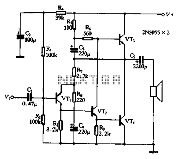
The circuit illustrated in Figure 240 is straightforward, utilizing only four transistors to process the input voltage, resulting in a large, inverted output. This configuration serves as a high-performance amplifier, delivering excellent high-fidelity power discharge capabilities. The input stage...
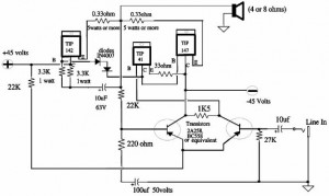
A 150W power amplifier circuit diagram utilizing power transistors TIP41, TIP142, and TIP147. The design is straightforward enough to construct without a printed circuit board (PCB). The power output range is approximately 100-150W. The 150W power amplifier circuit is designed...
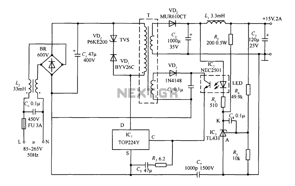
This circuit comprises a 15V TOP224Y, 2A output DC switching power supply. It utilizes three integrated circuits: IC1 is a monolithic regulator (TOP224Y), IC2 is an optocoupler (NEC2501), and IC3 is a precision voltage reference (TL431). The TL431 (IC3)...
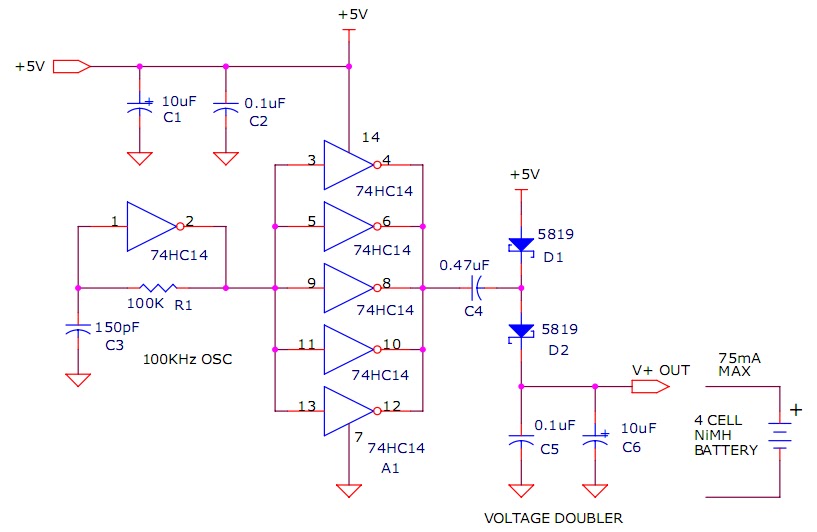
The circuit described will trickle charge a four-cell pack of AA or AAA NiMH batteries. It draws current from the +5V available from a USB connection and supplies approximately 70mA of current to the battery. This current level is...