
Power-line-modem
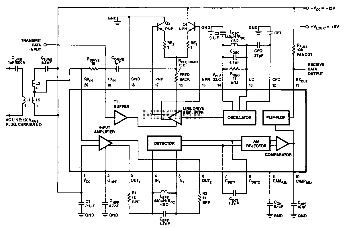
In the 100-kHz application, the coupling network feeds into the receiver section located at the bottom of the chip. The external components are summarized later. The receive data output is pulled up via a resistor (RPuLL) of approximately 10 kΩ. A minimum current of 10 mA establishes the voltage drop across RPuLL. Another voltage supply, VLoGJc, is indicated for users who prefer the output to be sent at TTL levels. The transmitter section is positioned at the top, with the oscillator network, the class AB output stage (noting the feedback resistor RFEEDBACK), and the drive section arranged from right to left. The LC values in the oscillator network should correspond to those in the bandpass filter of the receiver. The drive stage connects to the coupling network and returns to the receive section, facilitating on-chip collision detection with listen-while-talking capability. This effect can be canceled, although the transmitter remains connected to the receiver.
The circuit operates at a frequency of 100 kHz, utilizing a coupling network that serves as an interface between the transmitter and receiver sections of the chip. The receiver section, located at the bottom, is designed to receive and process incoming signals. The pull-up resistor (RPuLL), valued at approximately 10 kΩ, ensures that the output data line maintains a defined high state when no active signals are present. The minimum current of 10 mA flowing through RPuLL is critical for establishing the necessary voltage drop, which is essential for reliable data transmission.
In addition, the circuit includes an alternative voltage supply, VLoGJc, which allows the output signals to conform to TTL logic levels, making it compatible with various digital systems. The transmitter section, located at the top of the chip, consists of several key components arranged sequentially: the oscillator network generates the carrier frequency, followed by the class AB output stage that amplifies the signal while maintaining linearity and efficiency. The feedback resistor (RFEEDBACK) plays a crucial role in stabilizing the output stage by providing feedback to control gain and distortion.
The oscillator network's inductance (L) and capacitance (C) values are carefully selected to match those of the bandpass filter in the receiver section, ensuring optimal signal integrity and minimizing loss. The drive stage connects to both the coupling network and the receive section, enabling the functionality of listen-while-talking. This feature allows the circuit to detect collisions during transmission, enhancing communication efficiency. Although the collision detection effect can be disabled, the transmitter remains connected to the receiver, ensuring continuous monitoring and communication capabilities.In the 100-kHz application from left to right, the coupling network feeds into the receiver ~section on the bottom of the chip. (The external components are summarized later.) The receive data output is pulled up via RPuLL ~ 10 K!l.
A minimum current of 10 mA sets the voltage drop across RpuLL· Another voltage supply, VLoGJc, is shown if the user wants to have the output sent at TTL levels. Across the top is the transmitter section; going from right to left, the oscillator network, the class AB output stage (note feedback resistor RFEEDBAcK) and the drive section.
The LC values on the oscillator network should match those on the bandpass filter in the receiver. The drive stage feeds into the coupling network and back into the receive section. This enables the on-chip collision detection with listen-while-talking capability. This effect can be cancelled, although the transmitter will still be connected to the receiver. 🔗 External reference
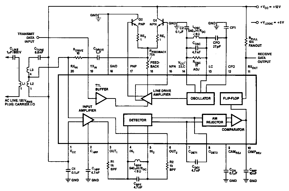
Related Circuits
In the 100 kHz application, the coupling network connects to the receiver section located at the bottom of the chip. The external components will be summarized later. The receive data output is pulled up through a resistor (RPuLL) valued...
Warning: include(partials/cookie-banner.php): Failed to open stream: Permission denied in /var/www/html/nextgr/view-circuit.php on line 713
Warning: include(): Failed opening 'partials/cookie-banner.php' for inclusion (include_path='.:/usr/share/php') in /var/www/html/nextgr/view-circuit.php on line 713