
Power Mosfet Inverter
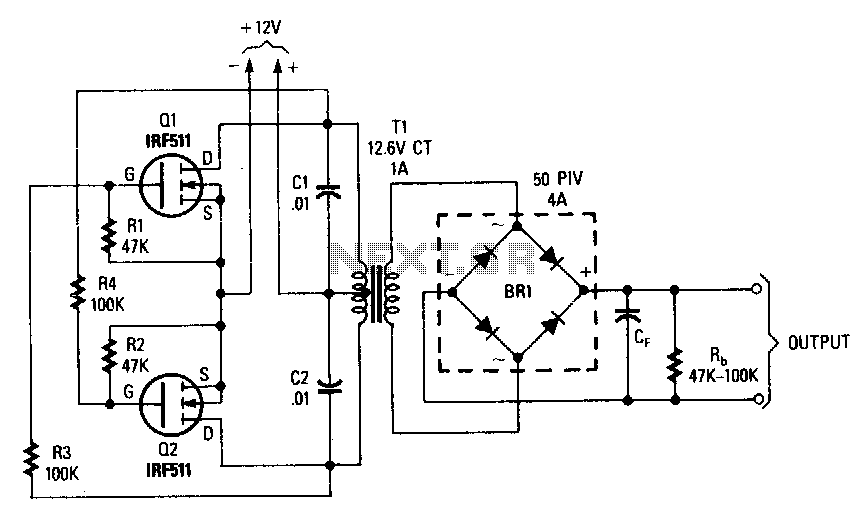
The inverter circuit described is designed to convert low-voltage DC into high-voltage AC or DC, suitable for various applications requiring high voltage output. The key components include a power transformer (T1), which is configured with its primary and secondary windings reversed. This configuration allows for flexibility in voltage transformation, enabling the inverter to operate effectively within a range of 12.6 to 440 volts.
Transistors Q1 and Q2, which are specified as power FETs (Field Effect Transistors), play a crucial role in switching the current through the transformer. The selection of appropriate FETs is critical for ensuring that the inverter can handle the required power levels without overheating or failing. Adequate heat sinking for Q1 and Q2 is essential to maintain operational stability and prevent thermal runaway, as these components will dissipate significant heat during operation.
Capacitors C1 and C2 serve as spike suppressors in the circuit. Their primary function is to mitigate voltage spikes that can occur during the switching process of the FETs. These spikes can potentially damage sensitive components or lead to erratic behavior in the inverter. By placing C1 and C2 in parallel with the FETs, the circuit is protected from transient voltages, enhancing reliability and longevity.
The overall design emphasizes the importance of thermal management and transient suppression to achieve a robust inverter capable of safely delivering high-voltage outputs. Proper layout and component selection are critical to ensure efficient operation and reliable performance in various applications.This inverter can deliver .high-voltage ac or de, with a rectifier and filter, up to several hundred volts. The secondary and primary of T1-a 12.6 to 440 V power transformer, respectively-are reversed; e.g., the primary becomes the secondary and the secondary becomes the primary.
Transistors Q1 and Q2 can be any power FET.
Be sure to heat sink Q1 and Q2. Capacitors C1 and C2 are used as spike suppressors.
🔗 External referenceRelated Circuits
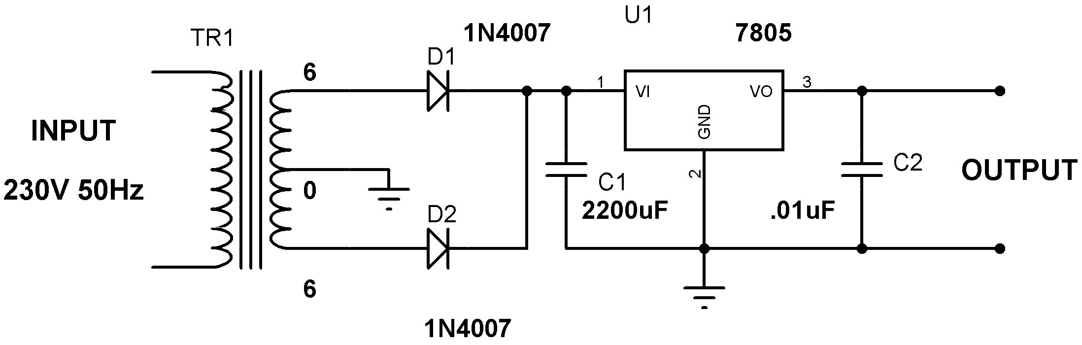
Designing a power supply requires careful consideration of each component. This discussion will focus on the design of a regulated 5V power supply. Note: Any transformer that provides a secondary peak voltage of up to 35V can be used;...
The circuit is based around LM4702 manufactured by NATIONAL semiconductors and MJ11029-MJ11028 by ON semiconductors. It is a high fidelity audio power amplifier designed for demanding consumer and pro-audio applications. You can also use this circuit with AV receivers,...
Modular power supplies are experiencing significant growth. The limitations in personnel for development engineers working on discrete solutions lead to increased costs, while readily available modules offer lower prices. Factors such as higher efficiency, easier certification, and the expertise...
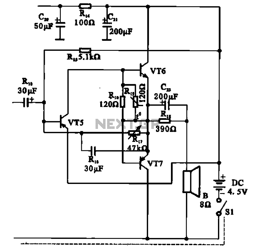
The transistor radio features a common output transformerless (OTL) power amplifier circuit. The VT5 component serves as the bias resistor for the driver stage. VT6 and VT7 form a complementary symmetry configuration, with VT6 being a germanium NPN transistor...
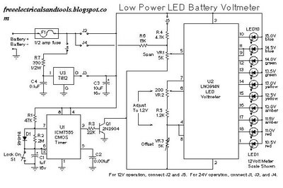
This is a low power voltmeter circuit designed for use with alternative energy systems that operate on 12V and 24V batteries. The voltmeter features an expanded scale that indicates small voltage steps within the 10 to 16 volt range...
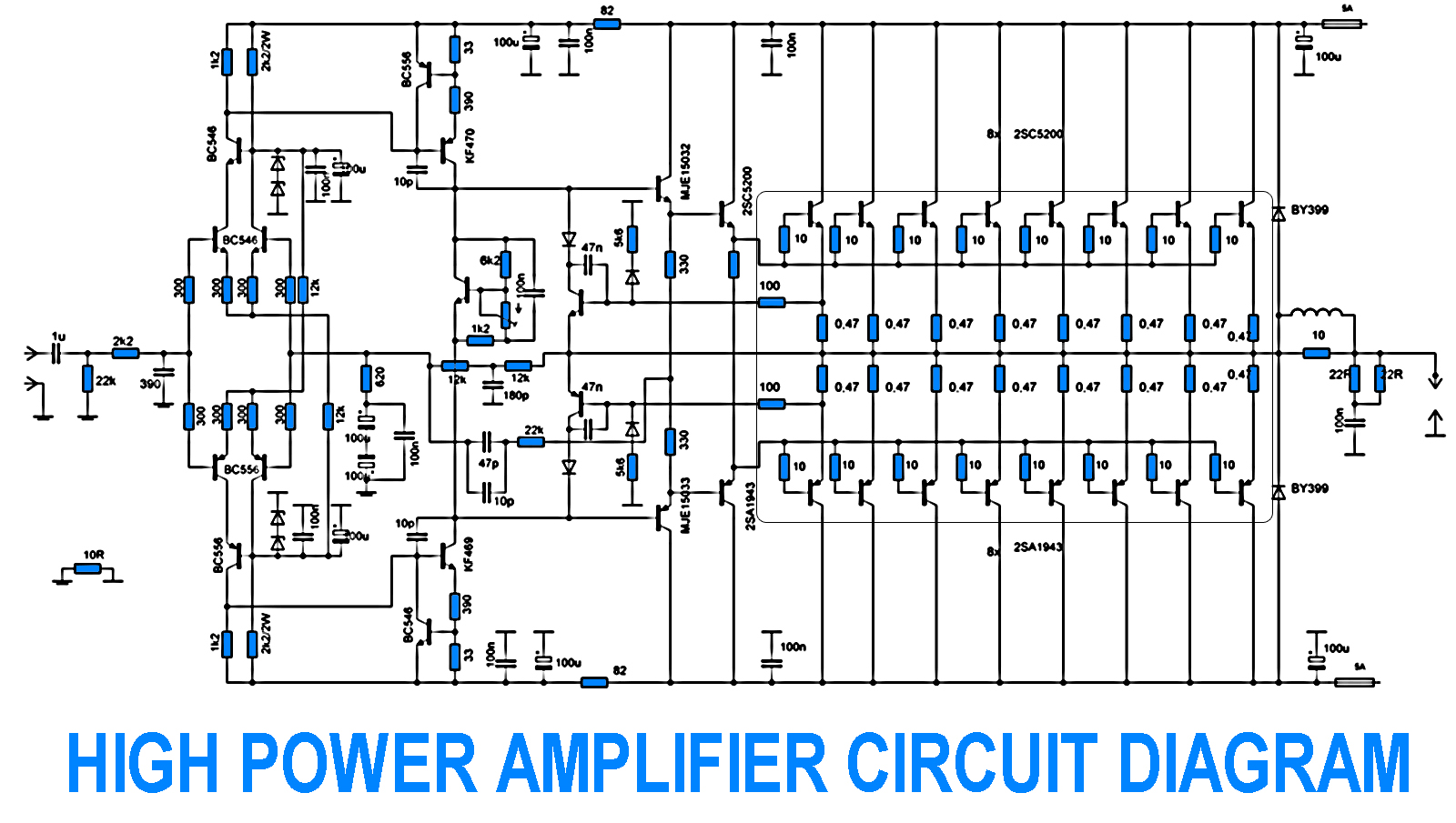
700W Amplifier. Adjusting the amplifier power to 700W appears straightforward, yet it is essential to consider the adjustment of the driving transistors and the frequency offset engagement. It is necessary to modify the current protection circuit that safeguards the...