
power MOSFET on/off switch -- asking for critique
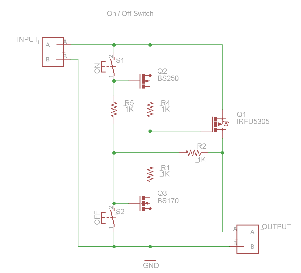
The proposed circuit design features a dual-button configuration for power control, utilizing a combination of three FETs to manage the on/off states effectively without the use of mechanical switches or relays. The configuration can be broken down into the following components and their functions:
1. **Power FETs**: The circuit employs a P-channel FET for switching the high side of the load. This FET will handle the main power flow to the device, allowing it to manage the peak current of 10 A. The choice of a P-channel FET is crucial for high-side switching, as it simplifies the control logic when interfacing with an MCU.
2. **Control FETs**: Two N-channel FETs are used to control the gate of the P-channel FET. When the "on" button is pressed, one of the N-channel FETs is activated, pulling the gate of the P-channel FET low, thus turning it on. Conversely, pressing the "off" button activates the second N-channel FET, which pulls the gate of the P-channel FET high, turning it off. This arrangement allows for efficient control of the load without the need for high current draw from the control buttons.
3. **Gate Pull-down Resistor**: A resistor is connected from the gate of the P-channel FET to ground to ensure that the FET remains off when no button is pressed. This weak pull-down will help maintain the circuit in a known state, preventing unintended activation due to floating gate voltages.
4. **Microcontroller Integration**: Future integration with an MCU will allow for soft control of the power state. The MCU can be programmed to activate the control FETs based on various conditions or commands, providing flexibility for remote or automated operations.
5. **Protection Features**: It is advisable to include additional components such as a flyback diode across the load to protect against voltage spikes, especially if the load is inductive. Additionally, incorporating a fuse rated appropriately for the load can provide safety against overcurrent situations.
6. **Debouncing and Filtering**: Although de-bouncing is not required in this instance, it is essential to consider the potential for noise in the system. Adding capacitors in parallel with the button inputs can help filter out any transient noise that may inadvertently trigger the FETs.
Overall, the circuit design presents a robust solution for managing power control in a LiFePO4 battery-powered device, balancing the need for low power consumption in the control logic with the ability to handle high current loads. Further refinement of the schematic for clarity and readability is recommended, ensuring that all connections are clearly marked and that the functional flow of the circuit is easily understood.A "power button" that is actually two buttons; one on, one off. This needs to switch on the order of 15 V and up to 10 A, for a LiFePO4 battery powered device. I don`t want to use a hardwired switch where this is mechanical, because I later also want soft (MCU-based) control of the same on/off functions. I don`t want to use a relay because60 mA for a typical coil current is a lot (the typical load is perhaps 500 mA, but peak load on the device is 10 A. ) This is the best I could come up with. De-bouncing the buttons is not needed. When first connected, I think it enters "off" state because the gate is weakly pulled to ground through the load (output) - and even if it isn`t, the main power P-channel FET isn`t going to have any gate charge. If you want to spend a few minutes helping out a poor n00b on circuit design, please critique this design and suggest whatever you think needs improving in this circuit.
(Three FETs really ) If you think my diagram is hard to read (I got that last time :-) then please at least critique exactly what you think is poor about the diagram, so that I can better communicate in the future. 🔗 External reference
Related Circuits
This circuit allows a 12v relay to operate on a 6v or 9v supply. Most 12v relays need about 12v to "pull-in" but will "hold" on about 6v. The 220u charges via the 2k2 and bottom diode. When an...
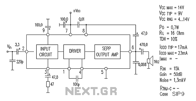
AN7112 power amplifier circuit diagram The AN7112 is a power amplifier designed for audio applications, capable of delivering high output power while maintaining high fidelity. The circuit diagram typically includes essential components such as transistors, resistors, capacitors, and a...
The first essential component for any workshop or lab is a power supply. When experimenting with various electronic circuit designs, having a flexible and adjustable power supply simplifies the process. Presented here is a design for an adjustable power...

The circuit is a high-power car audio amplifier schematic. It functions as a car audio amplifier using the PA02 and LH0101 integrated circuits (ICs). Each IC delivers an output power of 30W with an 8-ohm impedance. The part list...
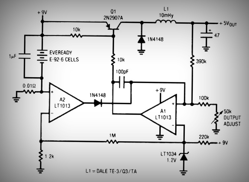
This circuit is a simple battery-powered switching regulator that provides a 5V output from a 9V source with 80% efficiency and a 50 mA output capability. When Q1 is on, its collector voltage increases, causing current to flow through...
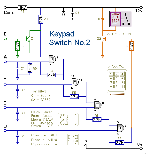
This is a simplified version of the 4-Digit Keypad Controlled Switch. The design has been modified to reduce circuit complexity and the number of components required. Consequently, the code is somewhat less secure, but it should be sufficient for...