
Adjustable 0-30V Power Supply
The adjustable power supply circuit based on the 723 voltage regulator is designed to provide a versatile and reliable source of power for various electronic experiments. The 723 IC is known for its high performance and stability, making it suitable for applications requiring precise voltage regulation. The inclusion of a Darlington pair (Q2 and Q3) enhances the output current capability, allowing the circuit to deliver up to 1A. This feature is particularly beneficial for powering components that require higher current levels.
The circuit's design incorporates essential safety features, such as the current limiting mechanism provided by variable resistor R3. This feature protects against potential damage caused by short circuits at the output. The adjustment of the zero point using potentiometer R11 and trimmer R12 is crucial for ensuring accurate voltage output. This calibration process must be performed carefully to achieve the desired performance.
The negative voltage supply, derived from the configuration of diodes D3 and D4, along with the stabilization provided by the 5.1V Zener diode, ensures that the circuit operates efficiently across the entire voltage range. The ability to set the output voltage to zero is particularly useful in various testing scenarios where a precise reference point is required.
In terms of physical construction, attention must be given to the PCB layout. Wider ground tracks are recommended to minimize resistance and potential voltage drops, which can affect performance. Additionally, adequate heat sinking for transistor Q3 is necessary to prevent overheating during operation, especially when supplying higher currents.
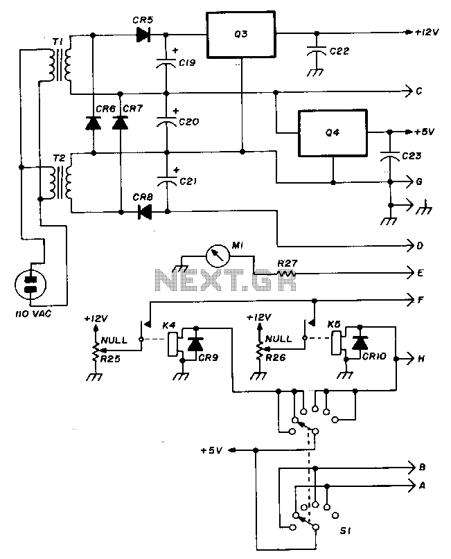
Overall, this adjustable power supply design represents a practical solution for electronic experimentation, offering flexibility and reliability for a wide range of applications.The first thing you must have in your workshop/lab is power supply. In experimenting many new electronic circuit design, it is easier if you have a flexible adjustable power supply. Here is an adjustable 0-30 volts power supply design. The circuit schematic diagram is shown below. The core of the circuit is 723 voltage regulator integrated circuit . A Darlington pair Q2 Q3 boost the current to give 1A output. The minimum voltage adjustment for this regulator IC is 2 volts above V-. Zero volt is achieved by supplying the V- with a voltage under -2V, so the output can be adjusted to zero. The negative supply is provided by the components around D3 and D4, stabilized by 5. 1 Zener diode. The variable resistor R3 is used to set the current limiter, so your power supply will be save even when you short its output to ground.
To set the zero point, turn the R11 potentiometer to minimum (counter clockwise) and adjust the R12 trimmer potentiometer until the output is zero. After this setting, turning the R11 potentiometer to the maximum will give around 30V output. If at the maximum position the output is smaller than 30V, it`s likely caused by the components tolerance, you can lower the R10 value.
Make sure you use larger track for ground connection on the PCB, and provide sufficient heat sink for Q3. 🔗 External reference
Related Circuits
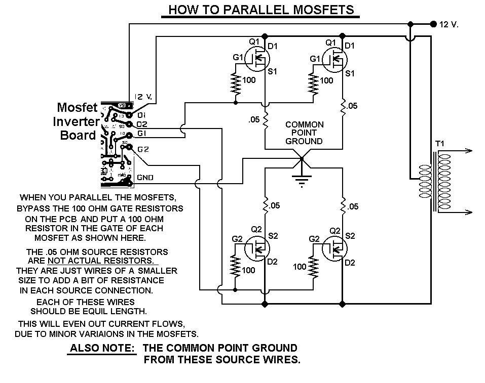
This 1000-watt power inverter circuit diagram utilizes the MOSFET RF50N06. To achieve higher power output, additional MOSFETs can be connected in parallel with the RF50N06. These MOSFETs are rated for 60 volts and 50 amps. It is essential to...
The TDA8932B/33(B) can operate with a symmetrical power supply. In this configuration, three half supply voltage buffers are disabled when powered from a symmetrical source. The TDA8932B/33(B) is a high-efficiency Class D audio amplifier designed for various audio applications. Operating...
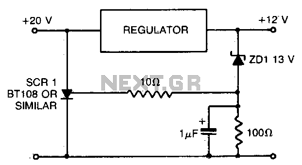
When using a regulated power supply to lower a supply voltage, there is always a risk that a failure in the power supply could result in a significant overvoltage condition across the load. To address overvoltage situations, the circuit...
The Hewlett-Packard HSCH-3486 zero-bias Schottky diode is utilized as the detector. To avoid employing a modulation detection method, a chopper-stabilized operational amplifier is implemented. The chopper operational amplifier effectively converts the input DC voltage to AC, amplifies it, and...

This method can be illustrated using an uncommon semiconductor power flip-flop. A flip-flop is a toggling circuit with two stable states (bistable multivibrator) that retains its output state without an input pulse. Triacs can be used to implement flip-flops...
The TDA2005 integrated circuit (IC) features a high output power of 10W per channel (stereo) at a load of 2 ohms with a distortion of 10%, and 20W in bridge mode at a load of 4 ohms with a...
Warning: include(partials/cookie-banner.php): Failed to open stream: Permission denied in /var/www/html/nextgr/view-circuit.php on line 713
Warning: include(): Failed opening 'partials/cookie-banner.php' for inclusion (include_path='.:/usr/share/php') in /var/www/html/nextgr/view-circuit.php on line 713