
Power Supply Unit
The PSU testing methodology described utilizes a sophisticated approach to ensure accurate and reliable results. The adjustable load with programmable control allows for precise manipulation of current, which is crucial for evaluating the performance of PSUs under varying conditions. The incorporation of MOSFETs in the design enhances the efficiency of current regulation, enabling a wide range of testing scenarios that can simulate real-world usage. The operational amplifier's feedback mechanism serves to maintain stability in the circuit, compensating for any thermal variations that may affect the output. This level of control is particularly important in high-wattage applications where even small fluctuations can impact performance metrics. Additionally, the use of high-quality components such as the IRFP264N transistors ensures that the testbed can handle significant power levels while maintaining safety and reliability. Overall, the detailed methodology and design considerations outlined in this article provide a robust framework for testing power supplies, contributing to the development of high-performance electronic devices.This article provides a detailed description of our methodology for testing power supplies in three major parts. The first one lists PSU parameters we check out and specifies the test conditions. In the second section you`ll find terms often voiced by PSU manufacturers for marketing purposes and their definitions.
The third part will be most inter esting for people who`d like to know how our PSU testbed is designed and operates. In our PSU tests our main task is to check it out at different loads, up to the maximum one. Many reviewers used to employ an ordinary PC for that purpose, installing the tested PSU into it. This method had two drawbacks: you had no control over the amount of power consumed by the PC, and it was hard to load a really high-wattage PSU. The second problem is especially crucial today when the PSU manufacturers have started a race for reaching as high a wattage rating as possible, and the capabilities of their products have by far exceeded the demands of a typical PC.
Of course, one may argue that there`s no point in testing PSUs at higher loads if no real PC needs more than 500W, but it would be odd not to check out a high-wattage PSU through its entire load range if we begin to test it at all. We use an adjustable load with programmable control to test PSUs in our labs. The testbed is based on the well-known feature of metal-oxide-semiconductor field-effect transistors (MOSFETs): a MOSFET limits the current flowing in the drain-source circuit depending on the voltage in the gate.
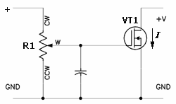
Above you can see a simple schematic of a MOSFET-based current regulator: connecting the circuit to a PSU with an output voltage of +V and turning the lever of the variable resistor R1 we are changing the voltage on the gate of the transistor VT1 thus changing the current I that flows through it from zero to maximum (determined by the characteristics of the transistor and/or tested PSU). This circuit is not perfect, though. When the transistor heats up, its characteristics change somewhat and the current I changes, too, although the control voltage on the gate remains the same.
To solve the problem, we need to add a second resistor R2 and an operation amplifier DA1 into the circuit: When the transistor is open, the current I flows through its drain-source circuit and through the resistor R2. The voltage on the latter equals U = R2*I, according to Ohm`s law. This voltage goes to the inverting input of the operation amplifier DA1. The non-inverting input of the same opamp receives the control voltage U1 from the variable resistor R1.
The opamp has such properties that it tries to maintain the same voltage on both its inputs by changing its output voltage, which in our circuit goes to the MOSFET`s gate and regulates the current flowing through it. Suppose the resistance R2 equals 1 Ohm, and we`ve set a voltage of 1V on the resistor R1. Then the opamp will change its output voltage in such a way that the voltage drop on the R2 is 1V, too.
The current I now equals 1V / 1Ohm = 1A. If we set a voltage of 2V on the R1, the opamp will react by setting the current I at 2A, etc. If the current I and, accordingly, the voltage on the resistor R2 changes due to the heating-up of the transistor, the opamp will immediately adjust its output voltage to bring them back. Thus, we have a perfectly controllable load that allows to smoothly change the current from zero to maximum with a turn of a lever.
It maintains the value you set automatically for as long as you wish. It is also compact, being much easier to handle than a clumsy set of low-resistance resistors connected in groups to the tested PSU. The maximum amount of power dissipated on the transistor is determined by its thermal resistance, the maximum allowable die temperature, and the temperature of the heatsink it is installed on.
Our testbed employs International Rectifier IRFP264N transistors (a 168KB. PDF file ) with an allo 🔗 External reference
Related Circuits
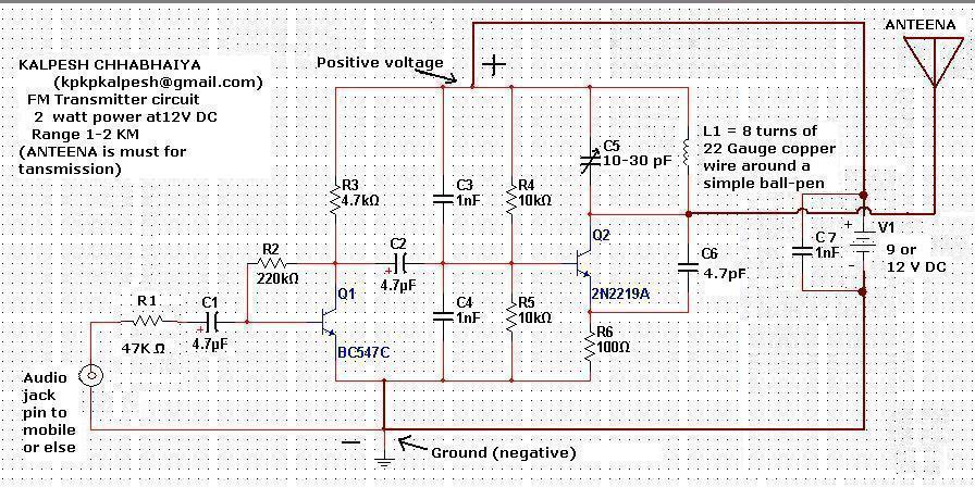
Constructing an FM transmitter for the first time can be challenging due to confusion regarding the necessary components, parts, design, PCB layout, and transmission aspects. An FM transmitter is an electronic device that encodes audio signals into radio frequency waves,...
The amplifier drives a pair of loudspeakers using two LM3876 integrated power amp ICs (50 watts per channel), or a pair of headphones via a Meier crossfeed filter and an OPA2134 dual opamp. It provides four switchable line level...
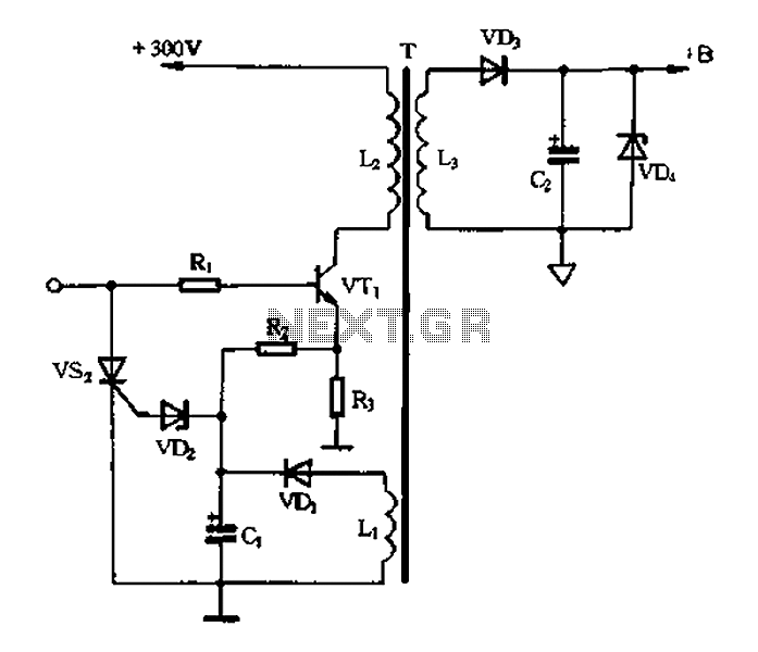
Color TV main power protection circuit The color TV main power protection circuit is designed to safeguard the television's power supply from various electrical anomalies, such as overvoltage, undervoltage, and short circuits. This circuit typically employs several components, including fuses,...
Amplifier with IC number TDA7293 for processing sound systems. This amplifier includes inputs for a radio, TV, stereo, or other line-level devices. It also features a phono input for a record player, guitar, microphone, or other unamplified sources. With...
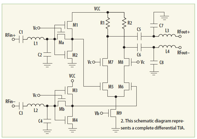
This transimpedance amplifier utilizes a current-reuse stage and a cascaded differential stage to provide a continuous gain tuning range of 15 dB, along with a low noise figure of 1.061 dB at 2.4 GHz. The transimpedance amplifier (TIA) is designed...
A person visiting the website is interested in a DC voltage adjustable regulator that can output between 1.2V to 12V with a current capacity of 1-2A. Initially, the individual considers using the LM317 integrated circuit for this purpose. However,...