
50 Watt power Amplifier with preamplifier and headphone output
The circuit described represents a well-engineered audio amplifier system designed to drive both loudspeakers and headphones effectively. The use of two LM3876 power amplifier ICs ensures that a substantial output power of 50 watts per channel is available for loudspeakers, while the integration of an OPA2134 op-amp in conjunction with a Meier crossfeed filter provides a refined headphone listening experience. The architecture consists of four distinct PCBs: one dedicated to each power amplifier channel, another for the power supply, and a third for the preamp and headphone driver.
The signal flow begins at the line-level inputs, which are switchable to accommodate various audio sources. The gain stage is designed to elevate the input signal sufficiently, allowing direct interfacing with the power amplifier stage. The implementation of a low-pass filter using C7 and R3 is critical for maintaining stability and controlling high-frequency gain, which is particularly important when substituting op-amps. The AC coupling capacitor C19 serves a dual purpose of setting the frequency response of the headphone amplifier and blocking DC offsets, which is vital for protecting the headphones and speakers from unwanted DC signals.
The headphone driver circuit is configured similarly to the main amplifier, ensuring that the audio signal is adequately amplified for headphone use. The crossfeed filter, which is hardwired into the circuit, facilitates a more natural listening experience by blending the left and right audio channels, which is beneficial for recordings originally intended for loudspeakers.
Further, the design incorporates protective elements such as R17, which serves to minimize load inconsistencies when headphones are not connected, thus preventing audible artifacts. The power amplifier section, utilizing the LM3876, is engineered to handle substantial output demands while providing low distortion and robust protection against thermal and electrical issues. The feedback network, composed of resistors and capacitors, is meticulously designed to ensure that the amplifier operates within optimal parameters, preventing oscillations and maintaining fidelity across the audio spectrum.
Overall, this amplifier circuit exemplifies a thoughtful integration of components and design principles aimed at delivering high-quality audio performance for both loudspeakers and headphones, making it suitable for a variety of audio applications.The amplifier drives a pair of loudspeakers using two LM3876 integrated power amp ICs (50 watts per channel), or a pair of headphones via a Meier crossfeed filter and an OPA2134 dual opamp. It provides four switchable line level inputs, and an unbuffered line level output for recording purposes.
The design uses readily available good quality components, and is based around four separate PCBs; one for each power amp channel, one for the power supply board, and one for the preamp/headphone driver. This initial gain brings the signal up to a level whereby the output from the volume control can drive the power amp circuits directly, with no further gain, and allows the headphone driver circuit to operate with a lower gain, giving lower noise performance. C7 forms a 100kHz low pass filter with R3, rolling off the gain to unity at very high frequencies, and helping promote stability of the opamp.
It is not strictly necessary with the suggested OPA2134 device, but allows the drop-in substitution of a cheaper but more oscillation prone device, such as the NE5532, if budgets are tight. C19 AC couples the output from this stage to the volume control, and with a 50k potentiometer, sets the -3dB point of the headphone amp's response at 1.4Hz (the power amp has further high pass filtering).
This capacitor is very important, as all the other stages are DC coupled, and C19 prevents any DC offsets from source components being amplified and presented to the headphones or speakers. The output of the pot feeds the power amp and the headphone driver, which is also mounted on the preamp board.
Looking at the above schematic for the headphone driver (figure 3), we can see that the opamp U2 is used in a similar configuration to the input amp U1. In this case, R24 matches as closely as possible the parallel combination of R11 and R12, helping reduce distortion as before.
Again, C21 allows compatibility with cheaper opamps. R11 and R12 set the gain of the stage at just over 3, bringing the signal up to a level sufficient to drive a pair of headphones. This stage also acts as a buffer, isolating the Meier crossfeed filter from the varying output impedance of the volume control.
C8, R14, (with C10, R21, and R15) form a crossfeed filter, which in this case is permanently wired in circuit. A detailed description of the operation of this circuit can be found in Jan Meier's article A DIY Headphone Amplifier with Natural Crossfeed.
Basically, the circuit performs a frequency selective mix of the two channels into each other, allowing recordings meant for speaker listening to sound natural on headphones. I had built projects with the filter made switchable in the past, but I never turned it off, so the switch was omitted here.
Finally, the opamp U3 forms a simple noninverting buffer to drive the headphones. R17 forms a minimum load when the phones are disconnected, and helps prevent pops and clicks when they are connected with the unit powered up. While it is possible to substitute cheaper opamps in other parts of the circuit, the device used here needs to have a high output current capacity, and must remain stable when driving difficult loads.
J10 and J12 are the output to the headphone socket, which should have its ground isolated from the chassis so as not to defeat the ground loop breaker circuit. Again, C11 to C18 provide local supply decoupling for the opamps. The circuit given here is similar to the one presented in the article, Single Chip 50 Watt / 8 Ohm Power Amplifier, on Rod Elliott's site, ESP.
The LM3876 is a good quality component capable of delivering 56W continuously into an 8 ohm load and 100W peak - enough for any dorm! It has a quoted distortion figure of 0.06% at 40W output, and offers good sound quality in a simple design.
It has comprehensive output protection circuitry, preventing not only thermal runaway, but protecting the device from short circuits on the output, and voltage spikes from inductive loads. Looking at the circuit, R3 and R1 set the gain of the power opamp at 23, and C1 limits the DC gain to unity.
It also forms a low pass filter with a -3dB point of 7.2Hz. R2 draws roughly 1.5mA from pin 8, disabling the internal muting function of the LM3876, and C2 provides a large time constant for the action of the muting circuit. R4 should be a 1W resistor, and has 10 turns of 0.4mm enamelled wire wound round it, with its ends soldered to the resistor leads, giving a roughly 0.7uH inductor in series with the 10 ohm resistance.
The inductor acts to promote stability of the power opamp, by ensuring a minimum 10 ohm load at higher frequencies. Likewise, the low pass zobel network formed by C7 and R5 (which should also be a 1W type), helps prevent oscillation should any RF appear on the output.
C3 to C6 provide local supply decoupling for the power amp IC. 🔗 External reference
Related Circuits
This circuit diagram represents an ECM Mic Preamplifier. It is a microphone amplifier compatible with Electret Condenser Microphones (ECM). The preamplifier exhibits an excellent dynamic range, capable of handling audio levels from a whisper to a scream; however, caution...
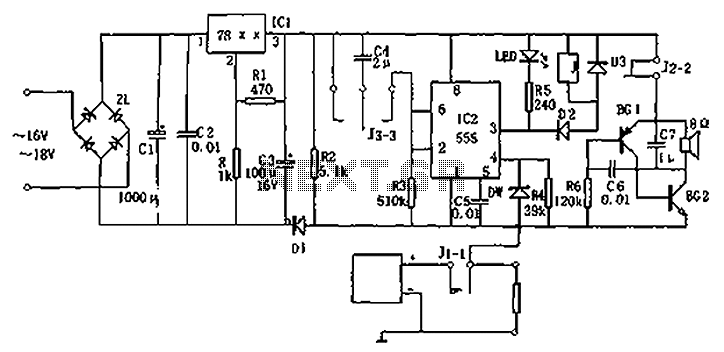
Circuit diagram for a DC power supply protection circuit. The device includes a buck rectifier power supply, a monostable delay circuit, a relay control circuit, and an audio feedback oscillation circuit. The entire circuit operates with a DC voltage...
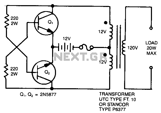
A simple 120 V to 24 V center-tapped control transformer, along with four additional components, can accomplish the task. This circuit produces a clean 200 V peak-to-peak square wave at 60 Hz and is capable of supplying up to...
This chapter includes circuit diagrams for various power supplies designed for pulsed solid-state lasers. It features units that are compatible with the widely used Hughes ruby and YAG rangefinder laser assemblies, one utilizing the flash from a disposable pocket...
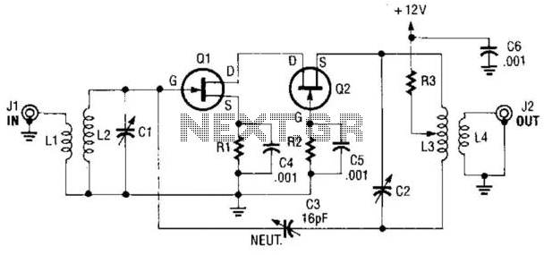
A cascode amplifier using two MOSFETs is illustrated in the diagram. L2C1 and L3C2 resonate at the operating frequency. The circuit offers advantages such as high gain, low noise figure (NF), and excellent linearity. Q1 and Q2 can be...
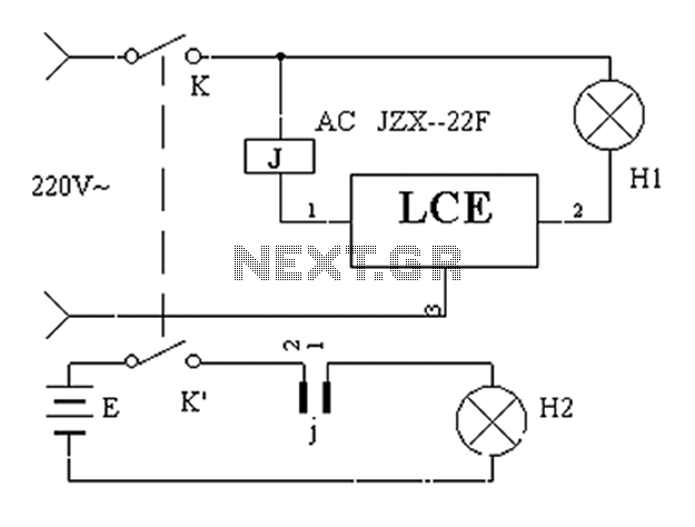
The application circuit operates the device as illustrated below, allowing for intermittent lighting in specific situations (e.g., during surgery). It utilizes an LCE module for blackout emergency lighting, which activates automatically after a power failure, ensuring uninterrupted illumination. In...