
Powerful Security Siren
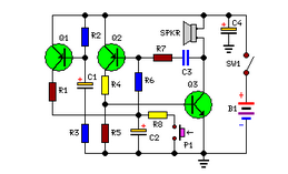
This circuit design utilizes a 12V battery as the primary power source and operates without any integrated circuits (ICs), making it straightforward and easy to assemble. The primary components involved include resistors, capacitors, diodes, and transistors, which collectively enhance the circuit's performance while maintaining simplicity.
The circuit can be configured to amplify power output, making it suitable for applications where increased power is necessary. The use of discrete components allows for greater customization and flexibility in terms of circuit parameters. For instance, selecting the appropriate transistor can significantly affect the gain and efficiency of the circuit.
The design typically includes a power stage that consists of a transistor configured in a common emitter or common collector arrangement, depending on the desired output characteristics. The base of the transistor is connected to a resistor divider network that sets the biasing point, ensuring that the transistor operates in the active region for linear amplification.
Capacitors may be employed for coupling and bypassing, helping to stabilize the circuit and filter out unwanted noise. Diodes can be included for protection against reverse polarity, ensuring the longevity of the circuit components when powered by the 12V battery.
This circuit is particularly advantageous for hobbyists and engineers looking for a reliable and efficient power amplification solution without the complexity of ICs. It serves as an excellent educational tool for understanding fundamental electronic principles, including amplification, biasing, and component interactions.Simple circuit No ICs required, 12V Battery operation This circuit was requested by several correspondents. Its purpose was to obtain more power than th.. 🔗 External reference
Related Circuits
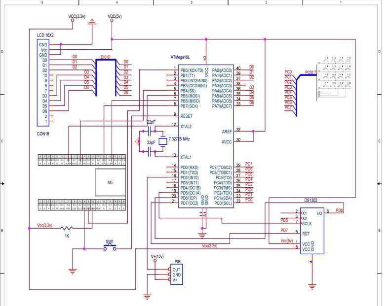
TCP based security system using the Ethernet module offered within the contest, an ATmega16L microcontroller, a PIR as a sensor and few other peripheral devices, which is specially targeted for homes and small business owners. I have used through...
Creating a modular, networked, home control system was greatly simplified by using common 4-wire phone cable with stake-on connectors. The cable feeds both power and network signals to the various modules. Each module is made on a single sided...
This circuit is designed for children's entertainment and is suitable for installation on bicycles, battery-powered cars, motorcycles, as well as in models and other games. When switch SW1 is positioned as indicated in the circuit diagram, it produces the...
This is an electronic siren circuit diagram. The sound produced imitates the rise and fall of an American police siren. When first switched on, the 10µF capacitors are discharged, and both transistors are off. When the push-button switch is...
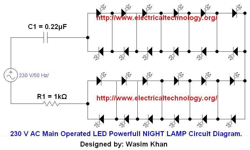
If you plan to use this circuit with a 110V 60Hz supply instead of a 230V 50Hz supply, or if you intend to modify this circuit, please refer to the section titled "Common Questions about this Circuit" found below...
The UM3561 features programmed mask ROM designed to simulate siren sounds. This integrated circuit operates at a low power consumption level and is powered by a 3-volt supply. An NPN transistor is utilized for the amplification of the audio...
Warning: include(partials/cookie-banner.php): Failed to open stream: Permission denied in /var/www/html/nextgr/view-circuit.php on line 713
Warning: include(): Failed opening 'partials/cookie-banner.php' for inclusion (include_path='.:/usr/share/php') in /var/www/html/nextgr/view-circuit.php on line 713