
230 V 50Hz AC (or 110V 60Hz) Main Operated LED Powerful NIGHT LAMPCircuit
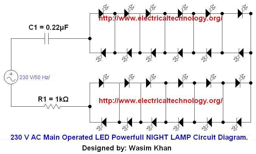
For the implementation of a circuit designed to operate at 110V 60Hz, it is essential to make specific adjustments to the components to ensure safe and effective operation. The circuit typically utilizes a capacitor (C1) that should be replaced with a 0.68 µF polyester capacitor rated for at least 250 volts. This change is crucial as it allows the circuit to handle the lower frequency and higher current associated with the 110V supply.
In addition to the capacitor modification, the resistor R1 must be adjusted to a value of 220 ohms with a power rating of 1/2 watt. This adjustment is necessary to maintain the appropriate current flow through the circuit, which is critical for the operation of the LEDs. The specified LEDs should be bright, operating at 3.2 volts and drawing 25mA, ensuring adequate brightness and visibility in the intended application.
The first circuit diagram provided serves as the primary reference for the correct configuration of these components. The second diagram, while included for experimental purposes, may not provide reliable results and should not be constructed in a typical home environment. Safety precautions must always be observed when working with electrical circuits, particularly when dealing with high voltage supplies. Proper insulation, component ratings, and adherence to electrical standards are vital to prevent any hazards or malfunctions.If you have plane to use this Circuit on 110V 60Hz instead of 230V, 50Hz, or want to modify this circuit, Then See the Section " Common Question about this Circuit" below the "instruction". Also Note that here is two circuit diagrams, so the first one is recommended. the second one (as i tried) is for experimental purpose only, so don`t trythe second one at home. i will be not liable for any Damage/Loss(es). Please be careful because your safety is better than everything. If Your plane is to use this circuit with 110V 60Hz AC main Supply then change CI to 0. 68 F (684 / 250Volts) polyester capacitor. Reduce the value of R1 to 220 © 1/2 watt. Ensure that you use 3. 2 volt 25mA Bright LED`s 🔗 External reference
Related Circuits
The resistance of the heater is constructed using 9 Ω nichrome wire with a diameter of 3 mm. When supplied with 240V (rms) voltage, this configuration results in a current of 25A (rms). Access to a mains line that...
The circuit involves powering an LED using a 3V CR2032 battery, with the intention of extending battery life by making the LED blink rather than remain continuously on. A 555 timer is considered, utilizing large value resistors in the...
The circuit illustrated in Figure 2-50 utilizes a field effect tube and a combination of electronic components to create a unique self-lighting controller. The working lamp remains illuminated at a reduced brightness rather than being completely turned off, which...
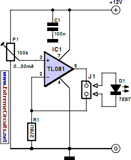
This simple LED tester consists of a current source with a potentiometer that can be used to adjust the current. The current source is implemented using a TL081 operational amplifier. The output current from the op-amp flows through the...
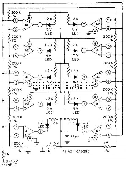
The circuit utilizes CA3290 BiMOS dual voltage comparators. The non-inverting inputs of A1 and A2 are connected to a voltage divider reference. The input signal is applied to the inverting inputs. LEDs are activated when the input voltage reaches...

This stereo amplifier utilizes the NE5517/A and features an excellent tracking accuracy of 0.3 dB, which is typical. The offset can be adjusted using the potentiometer, Rp. For AC-coupled amplifiers, the potentiometer can be substituted with two 5.1 k...