
Powerful Security Siren

This circuit design utilizes a complementary transistor pair, specifically Q2 and Q3, configured to function as a high-efficiency oscillator. This arrangement allows the circuit to drive a loudspeaker directly, producing a sound output without the need for integrated circuits (ICs). The design aims to enhance the power output compared to existing siren circuits, making it suitable for applications requiring a more robust audio signal.
Upon powering the circuit, Q1 plays a crucial role by ensuring that capacitor C2 is fully charged. The operation begins when the user presses switch P1, which initiates the discharge of C2 through resistor R8. This action causes the circuit to oscillate at a low frequency, which gradually increases. The frequency modulation continues until a high, steady tone is achieved, which can be sustained indefinitely as long as P1 remains engaged.
Releasing switch P1 leads to a gradual decrease in the output tone frequency. This occurs because C2 begins to recharge through resistor R6 and the Base-Emitter junction of Q2, allowing the circuit to transition back to a state of rest. The oscillation ceases once C2 is fully charged, resulting in a standby condition where the circuit remains inactive until the next activation.
The overall design emphasizes simplicity and efficiency, ideal for applications where minimizing component count and maximizing sound output are critical. The absence of ICs not only reduces complexity but also enhances reliability, making this circuit an attractive solution for various electronic projects.This circuit was requested by several correspondents. Its purpose was to obtain more power than the siren circuit already available on this website (One-IC two-tones Siren) and to avoid the use of ICs. A complementary transistor pair (Q2 & Q3) is wired as a high efficiency oscillator, directly driving the loudspeaker.
Q1 ensures a full charge of C 2 when power is applied to the circuit. Pressing on P1, C2 gradually discharges through R8: the circuit starts oscillating at a low frequency that increases slowly until a high steady tone is reached and kept indefinitely. When P1 is released, the output tone frequency decreases slowly as C2 is charged to the battery positive voltage through R6 and the Base-Emitter junction of Q2.
When C2 is fully charged the circuit stops oscillating, reaching a stand-by status. 🔗 External reference
Related Circuits

Crime in general is still on the rise, and having a security alarm installed is no longer a prerequisite of the wealthy. Here is a simple and compact security solution. A compact security alarm system can be designed to enhance...

The one-shot and decay functions could be added to create an ideal phasor gun sound. To design a circuit that generates a phasor gun sound using one-shot and decay functions, the following components and configuration can be utilized. The one-shot...
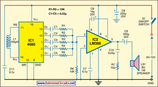
This multi-tone siren is beneficial for burglar alarms, reverse horns, and similar applications. It generates five distinct audio tones, making it significantly more attention-grabbing than a single-tone siren. The circuit is designed using the well-known CMOS oscillator and divider...
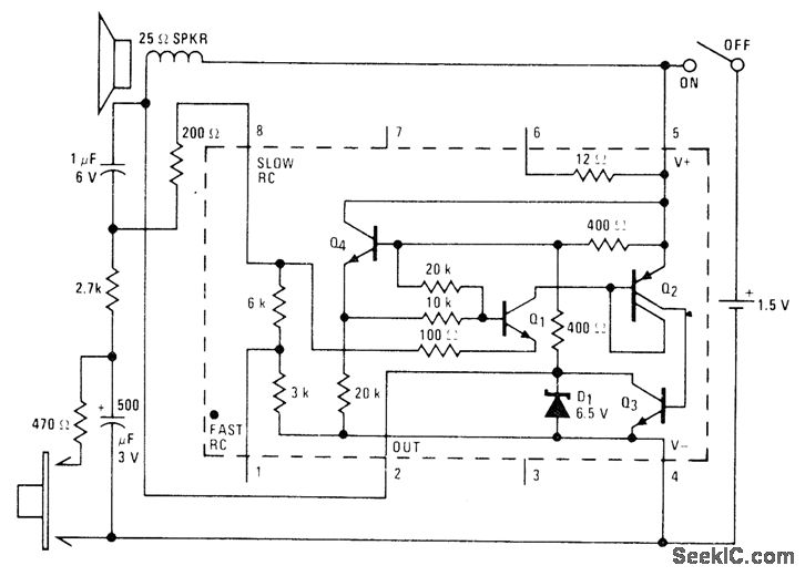
A low-drain circuit powered by a 1.5-V cell utilizes the National LM3909 flasher IC to simulate a fire-alarm siren. Pressing a button generates a rapidly increasing wail, with the tone decreasing in frequency once the button is released. The...
The security system application and program offers a simple demonstration of the BASIC Serial Interface. By adding only a few door and window switches, a transistor, a siren, and a few lines of BASIC program the interface can become...

This is a powerful siren circuit diagram. This circuit can provide significant support for alarm systems, enabling users to achieve optimal results. The siren circuit is designed to produce a loud sound for alerting purposes, commonly used in security systems,...