
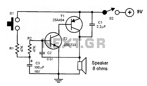
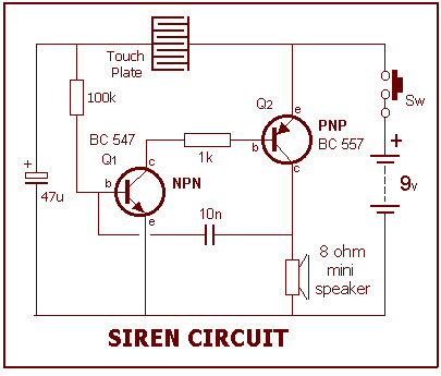
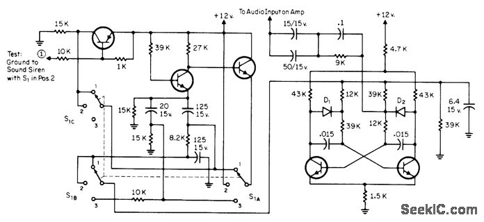
Siren for Factories

The siren circuit is designed to produce a loud sound for alerting purposes, commonly used in security systems, emergency alarms, or notification systems. The circuit typically consists of several key components, including a power supply, a triggering mechanism, an oscillator, and the siren itself.
The power supply provides the necessary voltage and current to operate the circuit. Depending on the application, this can range from a simple battery to a more complex AC power source. The triggering mechanism can be a switch, motion detector, or any other sensor that initiates the alarm when a specific condition is met.
The oscillator generates a frequency that drives the siren. This frequency can be fixed or adjustable, allowing customization of the sound produced. An integrated circuit (IC) or a simple transistor-based design may be employed to create the oscillator. The output from the oscillator is fed into the siren, which converts the electrical signal into sound waves.
In addition to these components, the circuit may include resistors, capacitors, and diodes for signal conditioning and protection. Proper selection of these components is critical to ensure the reliability and performance of the siren circuit. The design may also feature a volume control or a tone generator to provide different sound patterns, enhancing the effectiveness of the alarm.
Overall, this powerful siren circuit serves as a vital component in alarm systems, providing audible alerts that can deter intruders or notify individuals of emergencies.This is powerful siren circuit diagram. You can get lots of supports from this circuit because you can use this circuit for your alarm circuit then you will be able to get maximum results. 🔗 External reference
Related Circuits
A robber will not remain in an area with an ear-piercing sound, as they cannot hear if someone is approaching. It is the best deterrent available. The "F" contact on the piezo is "feedback" and is not required in...
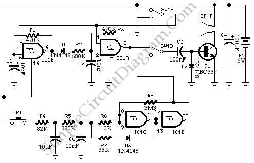
This circuit generates a double tone police sound and a single tone old ambulance sound. It is typically installed in battery-powered cars and motorcycles. The circuit utilizes a sound generator IC, such as the 555 timer or a dedicated sound...
This project is built on the third section of the PC board, identified by "SIREN" and "Project 5." You will notice the similarity between this circuit and the LED FLASHER circuit from project 2. The only differences are the...
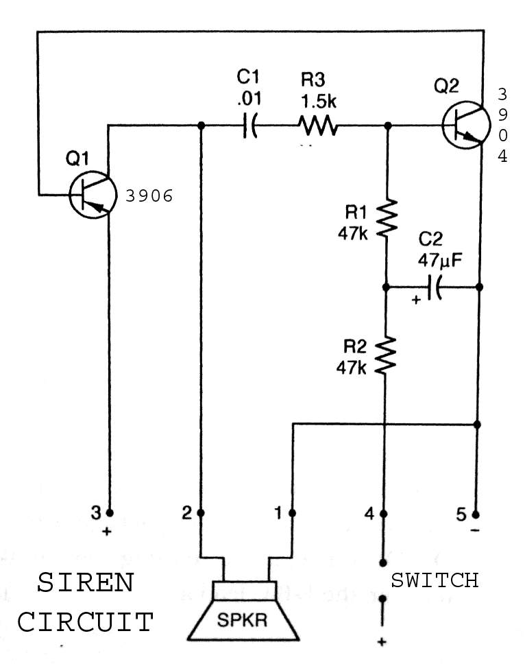
3904 3906 Siren Circuit. The circuit generates a wailing siren sound when the switch is activated. The 3904 3906 Siren Circuit is designed to produce a distinctive wailing sound, commonly used in alarm systems and signaling devices. The circuit utilizes...
The circuit utilized in the Dietz siren-light police car system produces distinctive audio tones. The switch S1 has multiple positions: Position T generates a slow, continuous rise and fall in tone. Position 3 creates a fast rising and falling...

This circuit produces a siren-like sound similar to that of ambulance sirens. Unlike traditional ambulance siren circuits that typically use an IC 555, this design employs transistors, making it more economical and easier to customize. The operation of the...