
Pre MIC (microphone preamplifier) 2 CH by IC NE5532 or LF353
%2B2%2BCH%2Bby%2BIC%2B%2BNE5532%2Bor%2BLF353.jpg "Pre MIC (microphone preamplifier) 2 CH by IC NE5532 or LF353")
The microphone preamplifier circuit, designated as a 2-channel design, is engineered to enhance audio signals captured by dynamic microphones. The selection of NE5532 or LF353 integrated circuits is pivotal in achieving low noise levels and high fidelity in sound reproduction. These components are known for their excellent performance in audio applications, providing a significant gain to the microphone signals before they are sent to a stereo power amplifier.
The circuit operates on a dual power supply, requiring +12V and -12V, which is essential for the proper functioning of the op-amps within the integrated circuits. This bipolar power supply configuration helps to maintain signal integrity and reduces distortion, ensuring that the amplified output maintains the quality of the original sound.
The inclusion of variable resistors, VR1 and VR2, allows for precise adjustments to the audio signal. These potentiometers can be used to control gain and tone, enabling users to customize the sound according to their preferences or specific application requirements. This feature is particularly beneficial in live sound environments or recording settings where sound characteristics may need to be tailored.
The overall design of the circuit emphasizes simplicity and effectiveness, making it suitable for various audio applications, including music production and public address systems. The printed circuit board (PCB) layout, referenced in the original description, provides a clear visual guide for assembly and helps to ensure that all components are correctly positioned for optimal performance. The combination of high-quality components and thoughtful design makes this microphone preamplifier a reliable choice for audio enthusiasts and professionals alike.This be Pre Mic circuit or Microphone preamplifier circuit model 2 CH. By this circuit uses integrated number circuit NE5532 or LF353. It perform enlarge sound signal from Dynamic Micro phone give the power goes up for subsequently submit to go to still stereo power amplifier circuit next. This circuit be of good quality good sound, because of use the integrated circuit decreases the noise, but should use the fire feeds +12V GND -12V with. The VR1 and VR2 perform fine decorate the sound. The detail is other and PCB see in a picture below. 🔗 External reference
Related Circuits
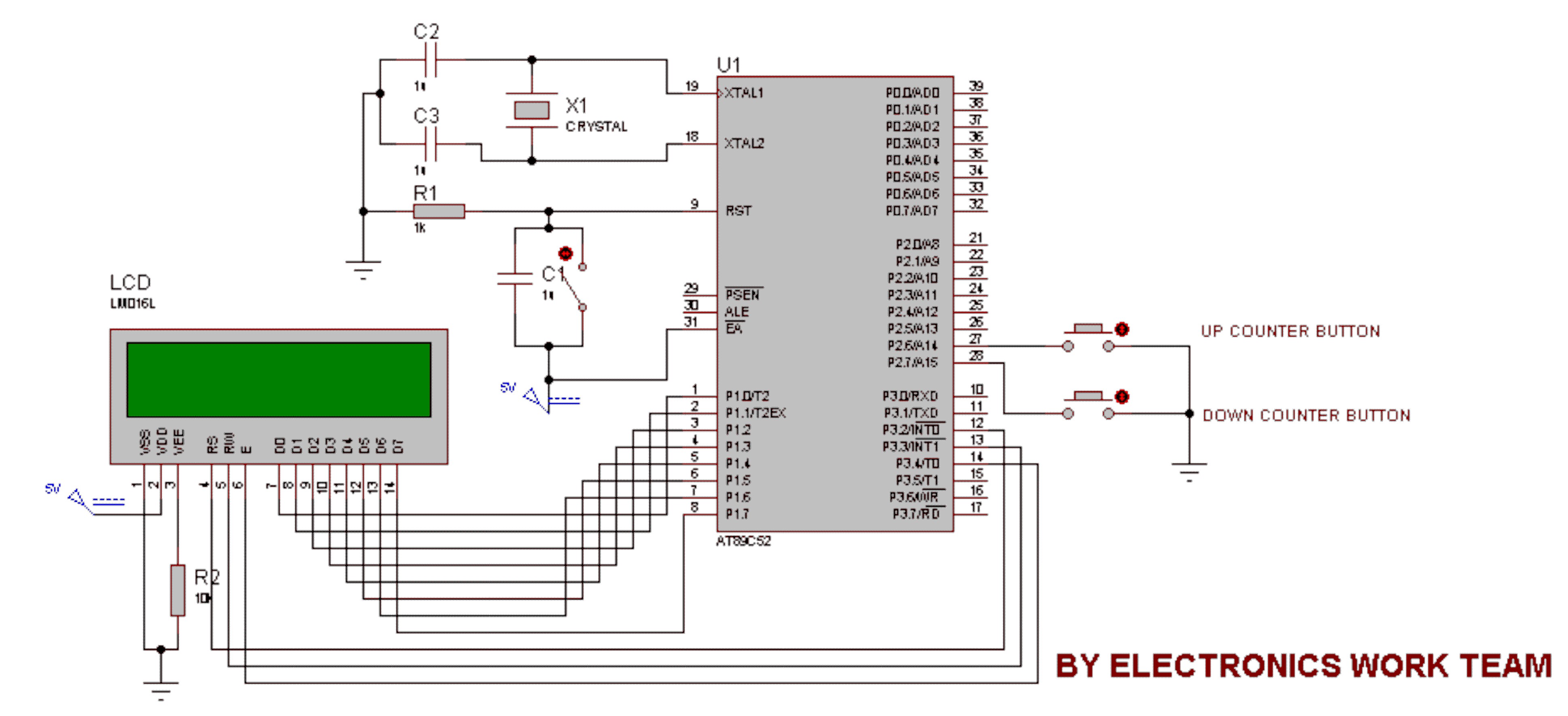
This circuit utilizes a 16x2 LCD to display a count value using an 8051 microcontroller. The maximum count value is set to 99. The circuit consists of the 8051 microcontroller, a 16x2 LCD, and two switches designated for incrementing...

This page is a work in progress. The board and source files will soon be available for building and programming to play custom songs. After assembling the board, communication with the programmer was verified, and both the LED and...
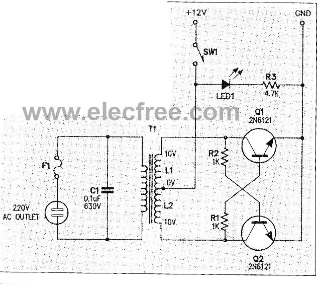
This micro inverter is a small-sized device that modifies energy from a battery, producing an output voltage of approximately 220V AC at 50Hz. The circuit comprises two transistors that function as a pulse oscillator or square wave generator, driving...
A stereo valve phono preamplifier has been constructed by a technician. The device requires a power transformer and various components, excluding the valves, which the technician recommends sourcing based on individual needs. Experienced DIY enthusiasts are invited to share...
This is a simple microphone preamplifier circuit which you can use between your microphone and stereo amplifier. This circuit amplifier microphone suitable for use with normal home stereo amplifier line/CD/aux/tape inputs. This mic preamp can take both dynamic and...
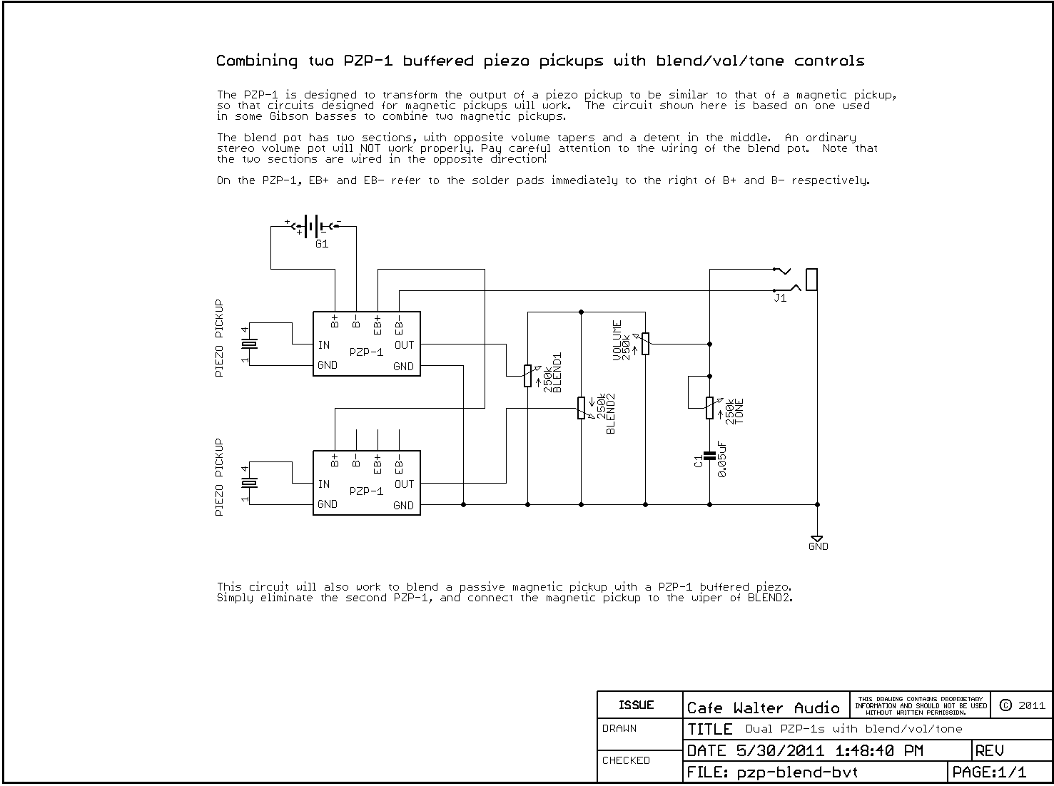
The PZP-1 Piezo Buffer is now available. It is a high-impedance buffer preamp that utilizes 100% discrete class-A circuitry. Specifically designed for the Fender Precision acoustic/electric and HMT basses, it can also enhance the performance of other instruments equipped...