
Micro Inverter by 2N6121
The micro inverter circuit is designed to be compact and efficient, making it suitable for various low-power applications. The use of a pulse width modulation (PWM) technique can further enhance the inverter's performance by allowing for finer control of the output voltage and frequency. By adjusting the RC components, the frequency of the output wave can be tailored to match the requirements of specific devices, ensuring optimal performance and compatibility.
In constructing the inverter, careful attention must be paid to the selection of transistors. Transistors with similar current gain characteristics are preferred, as they ensure balanced operation in the push-pull configuration. This balance is critical for minimizing distortion in the output waveform and maximizing the efficiency of the transformer.
The transformer plays a vital role in stepping up the voltage from the low DC level to the required AC level. A universal transformer with a center tap is ideal for this application, as it allows for easy implementation of the push-pull switching method. The design should also consider thermal management, as the transistors can generate heat during operation. Adequate heat sinking and ventilation must be provided to ensure reliable operation over extended periods.
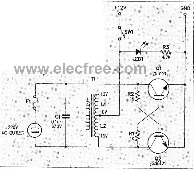
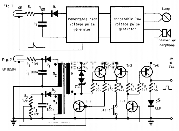
The overall design emphasizes simplicity and ease of assembly, making it accessible for hobbyists and engineers alike. The use of standard components and straightforward wiring techniques allows for rapid prototyping and testing. Safety precautions should be taken during assembly and operation, particularly in checking for short circuits and ensuring proper insulation between components to prevent electrical hazards.This is Micro inverter or The inverter very small-sized, perform modify from the energy battery the small-sized, have the value voltage about 220V AC Volt 50HZ. By the circuit composes 2 transistors performs pulse oscillator generator or Square wave generator, for drive the coil transformer have voltage tall about 220V at 50Hz frequencies.
By can change the value RC when give the frequency can modify. This circuit have current about 100mA depend on the transistor and Transformer. The detail is other total up PCB see in a picture below. A voltage converter DCV into ACV always called that inverter circuit . Which this micro inverter circuit very tiny, acts as convert voltage from the 12 VDC battery to ACV in range of 180V to 220 V-AC, by have frequencies in range of 30Hz to 65 Hz. And can be used with a general electric devices so current consumption under 10 watt. Such as a small compact fluorescent, a CD player, a general small radio, as more popular than incandescent bulbs because the light-colored eyes and saves more power.
This inverter project use a universal transformer with a dual power transistors. We easily assemble all parts with wiring the joint only, because a small projects, so you`ve succeeded in making a good inline solder connection within five minute. The normally DC to AC converting circuit will include the oscillator circuit, that uses the source voltage is 12 Volts-DC, then drive current through a center trap coil.
By uses dual power transistors is a push-pull switching (working alternates) Both transistors should have current gain rates similar, but not necessarily equal When we apply voltage are in to this project. An one transistor will be saturation point (close circuit) faster than other, to set Q1 close circuit before.
The collector current of Q1, Therefore, to create a magnetic field in the. L2-coil then get a base voltage more through a R1-resistor. The Q1-transistor so into the close circuit state fast and making Q2 open circuit faster as well. This manner condition remained until the transformer core to saturation. Therefore, cause current flowing through R1 reduce until not enough makes Q1 is in close circuit state. On the contrary, while Q1 begins to change slowly. From the close circuit into opent circuit that, The Q2 also will start conductor higher. The current flowing through R2 will add bias to Q2, makes Q2 close circuit faster. Now the current from battery will flow reverses the direction in the coil-L1. Cause the induced voltage polarity is reversed in the secondary coil of transformer, Q2 will still conductor until transformer core to saturation point.
1. Use a mica insulator insert between case and body of transistor, then use a plastic insulator acts as hold the transistor body with hex nut and metal screw (as Figure 3) 3. Use ohmmeter check short circuit of various devices, does not short circuit with case. By used VOM set Rx1 range then point at leads of device, It must not read as 0 ohms. as Figure 4. 🔗 External reference
Related Circuits
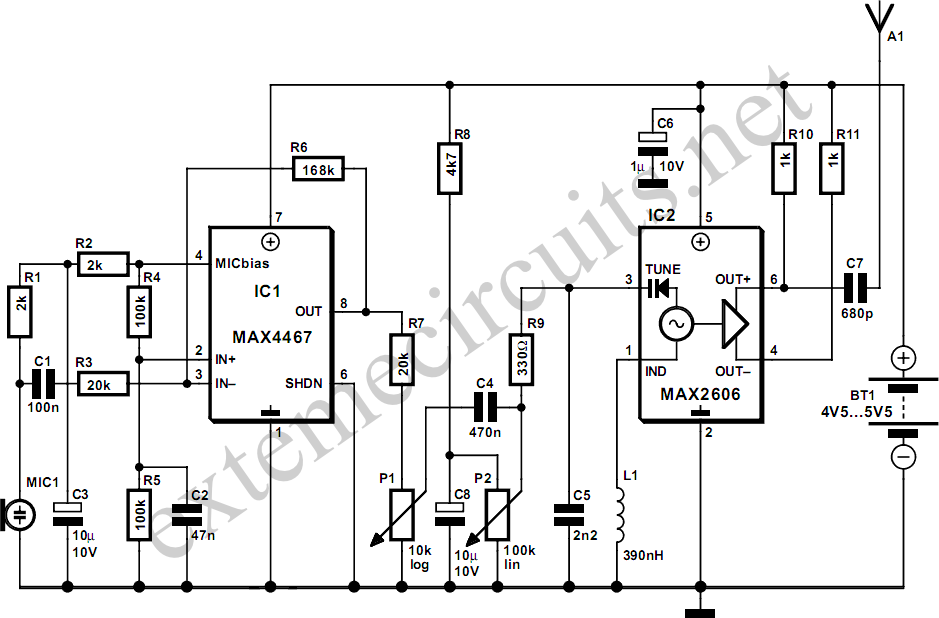
This project involves a simple and cost-effective transmitter that allows for speech transmission over a short range, functioning effectively as a cordless microphone. The circuit utilizes two integrated circuits from Maxim. The first, IC1, is the MAX4467, which amplifies...
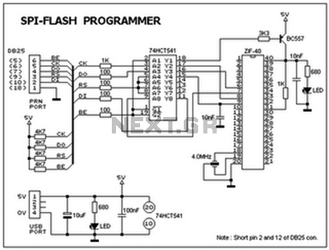
This ISP programmer can be utilized for both in-system programming and as a standalone SPI programmer for Atmel ISP programmable devices. The programming interface is compatible with the STK200 ISP programmer hardware, allowing users of STK200 to employ the...
This preamplifier uses a type of IC 741 and can boost a microphone signal to line level. The microphone signal is connected to the input port. Any power for the microphone jack of the food are met. Here half...
In the absence of radiation, no current is drawn. At normal background radiation levels, the power consumption is extremely low. The instrument may be left on for several months without changing batteries. In this way, the detector is always...
Dynamic microphones utilize a moving coil within a magnetic field to convert mechanical movements into electrical signals. An ordinary mini speaker can be transformed into a... Dynamic microphones operate on the principle of electromagnetic induction. When sound waves hit the diaphragm...
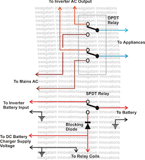
This inquiry has been presented multiple times on this blog regarding the implementation of a changeover selector switch for the automatic toggling of an inverter when AC mains power is available, and vice versa. The system must also enable...