
preamp
The preamplifier circuit is structured to provide optimal performance for bass guitar applications, where high input impedance and low output impedance are critical for maintaining signal integrity. The use of MPSA18 transistors ensures reliable operation and good thermal stability, while the FET in the first stage allows for a significant input impedance, which is essential for preventing signal loss from the bass guitar.
The circuit can be divided into three main sections: the input stage, the gain stages, and the output stage. The input stage employs a FET, which is known for its high input impedance characteristics. This is crucial for interfacing with passive pickups from the bass guitar, as it minimizes loading effects that could degrade the signal quality. The first gain stage is configured to amplify the signal while maintaining a linear response, with a targeted gain of 2.5.
Following this, the second gain stage further boosts the signal, contributing an additional gain of 4. The design of the second stage includes a buffer transistor, which effectively lowers the output impedance to match the input requirements of the subsequent power amplifier. This ensures that the signal can drive the power amplifier without distortion or loss of fidelity.
The power supply design is also noteworthy. The choice of a 24V supply, regulated by an LM7824, ensures that the circuit operates within a stable voltage range, which is essential for consistent performance. The LM7824 provides a reliable voltage regulation, minimizing fluctuations that could affect the preamp's performance.
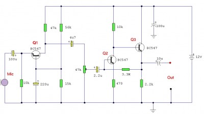
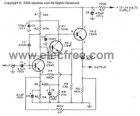
Overall, this preamp design is a practical solution for bass players seeking a clean and reliable amplification stage, combining thoughtful component selection and circuit topology to achieve desired audio characteristics.This is a clean preamp that I designed to use with my bass, a power amp, and a cab at a rehearsal space. (Rehearsal space being a fancy name for the singers basement. ) I am very proud of this preamp since, unlike the mu-preamp, I designed it from the ground up. Although there is nothing special about the design, at least it is all mine. The desig n started as an all transistor design using only MPSA18s. ( Original design ) The original design had three stages: input buffer, first gain stage, second gain stage. I did not design the input buffer, I got it from the Acoustic Control 360 Bass Preamp schematic. I breadboarded the original design and it worked. Then I realized that a FET could provide both the high input impedance and the first gain stage. So I switched to the current design. And got rid of the part I did not design in the process. You may notice that the every stage has paired transistors. The second transistor acts as a buffer. For the first stage, it provides a high impedance to the FET to maximize its gain. For the second stage, the buffer is required to provide a nice low output impedance for the power amp.
The power amp I am using has a 10K input impedance. I measured the output impedance of the NPN gain stage without the buffer at about 3. 5K. With the buffer it is about 16 ohms. Much better. The first stage is designed for a gain of 2. 5 and an Ids of about 1mA. The second stage is designed for a gain of 4 and an Ic of 5mA. This provides a gain of 10 which is 20dB. I chose a 24V supply voltage because that is the largest wall wart style supply that is easy to get. The 24V supply I used produces close to 32V at the low current used by the preamp. I used an LM7824 to regulate the voltage to 24V. 🔗 External reference
Related Circuits
This is an audio preamplifier for dynamic microphones with an output impedance of 200-600 ohms and a low-noise pre-amplifier ideal for signal strengthening. It features a three-stage discrete amplifier with gain control. Transistor alternatives such as BC109C, BC548, BC549,...
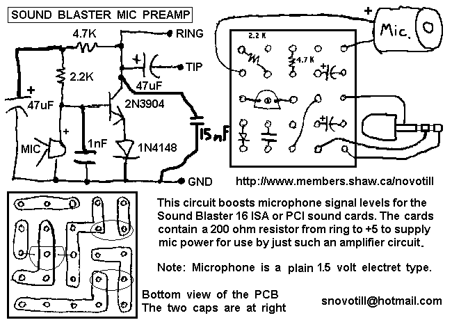
The Sound Blaster 16 PCI and Sound Blaster 16 ISA do not have a very sensitive microphone input. This little one transistor amplifier is powered directly from the microphone jack on the sound card and has LOTS of gain....
Greetings to everyone. I am new to this forum, although I have previously used it to create a DIY projector. My knowledge of electronics is limited, and I am currently reading books to improve my understanding. The creation of a...
The circuit diagram of a guitar preamplifier is designed to accept any standard guitar pickup and features two signal outputs. A typical example of a pickup attached to a guitar headstock is illustrated. The pickup device consists of a...
The objective is to enhance information transmission by utilizing articles. Please contact us via email at [email protected] within 15 days if there are issues related to article content, copyright, or any other concerns. The content will be removed promptly. To...
This is a simple microphone preamplifier circuit which you can use between your microphone and stereo amplifier. This circuit amplifier microphone suitable for use with normal home stereo amplifier line/CD/aux/tape inputs. This microphone preamplifier can take both dynamic and...