
preamplifier for ecm microphone
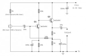
The described circuit is a low-noise microphone preamplifier designed to amplify signals from an electret condenser microphone (ECM). The use of low-noise transistors, such as the BC549C or BC109C, enhances the overall performance by minimizing unwanted noise in the signal path. The circuit's self-stabilizing nature allows it to maintain a consistent quiescent point, which is crucial for optimal signal amplification and dynamic range.
The electret condenser microphone is a key component, featuring a highly sensitive microphone element and an internal FET preamplifier. The power supply requirements for the circuit range between 2 to 10 volts DC, ensuring compatibility with various ECMs available in the market. The inclusion of a 1k resistor limits the current flowing to the microphone, and adjustments to this resistor are necessary when operating at higher supply voltages to prevent damage to the microphone.
The first stage of amplification, centered around transistor Q1, operates at a low collector current, which is advantageous for achieving a high signal-to-noise ratio. The decoupling of the emitter resistor with a 100µF capacitor maximizes the gain for this stage, allowing for effective noise reduction. The design is optimized to ensure that the noise response remains low, as evidenced by measurements taken across a 10k load.
The second stage, utilizing transistor Q2, is direct-coupled to minimize phase shifts and achieve a flat frequency response across a wide range of audio frequencies, from 20Hz to over 100kHz. Feedback from the emitter of Q2 to the base of Q1 ensures that the biasing of the transistors remains stable under varying temperature conditions, further enhancing the reliability of the circuit.
In emitter follower mode, Q2 provides an output that is suitable for driving long cables without significant signal loss, making the use of screened cables unnecessary. The overall voltage gain of approximately 100x or 20dB indicates a robust amplification capability, allowing the preamplifier to handle a wide range of sound levels, from soft whispers to loud shouts, while ensuring that downstream audio equipment is not overloaded. This circuit exemplifies a well-designed low-noise preamplifier suitable for various audio applications.Both transistors should be low noise types. In the original circuit, is used BC650C which is an ultra low noise device. These transistors are now hard to find but BC549C or BC109C are a good replacement. The circuit is self stabilizing and will set its quiescent point at roughly half the supply voltage at the emitter of Q2. This allows maximum out put voltage swing and also the highest dynamic range. The electret condenser microphone (ECM) contains a very sensitive microphone element and an internal FET preamp, a power supply in the range 2 to 10 volts DC is therefore necessary. Suitable ECM`s may be obtained from Maplin Electronics. Although the schematic is drawn showing a three terminal ECM, two terminal ECM`s may be used, the following page in the practical section shows the changes.
The 1k resistor limits the current to the mic. This resistor should be increased to 2k2 if a supply voltage above 12 Volts DC is used and is not needed if the Mic insert is dynamic. The first stage amplifier built around Q1 is run at a very low collector current. This factor contributes to a very high overall signal to noise ratio and low overall noise output. The emitter resistor of Q1 is decoupled by the 100u realizing a maximum gain for this stage. The noise response of the amplifier measured across the 10k load is shown below. Please note that this plot was made with the mic insert replaced by a signal generator. The second stage, built around Q2 is direct coupled, this minimizes phase shift effects (introduced with capacitive and inductive coupling methods) and acheives a flat output response from 20Hz to over 100kHz.
The frequency response measured across a 10k load resistor is plotted below simulated using a 12V power source: The emitter voltage of Q2 is also fed back to the base of Q1 via resistive coupling. This also ensures bias stabilization againt temperature effects. Q2 operates in emitter follower mode, the voltage gain of this stage is less than unity, however, the overall voltage gain of the preamplifier is about 100x or 20dB as shown in the bode plot above.
The output impedance is very low and well suited to driving cables over distances up to 50 meters. Screened cable therefore is not necessary. This preamplifier has excellent dynamic range and can cope with anything from a whisper to a loud shout, however care should be taken to make sure that the auxiliary equipment i. e. amplifier or tape deck does not overload. 🔗 External reference
Related Circuits
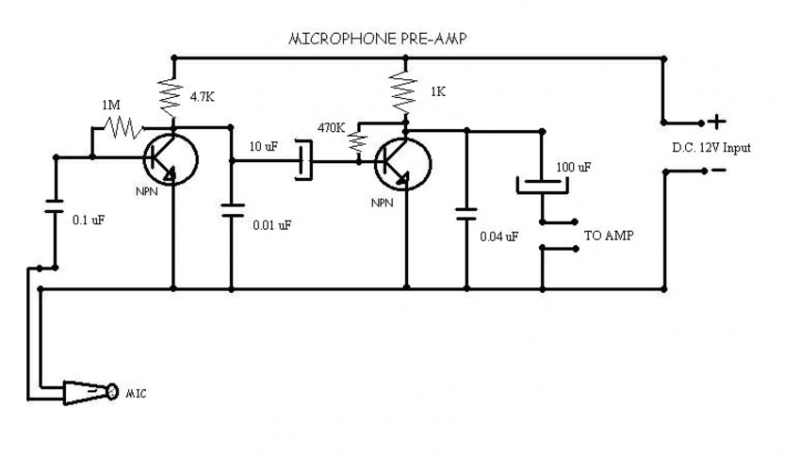
This circuit is used to give out a microphone preamp to an amplifier which will power the signal. The NPN transistors used are ECG123A. This circuit is also an older model to the one that now uses IC's,...
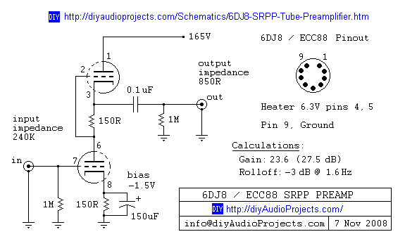
6DJ8 / ECC88 Symmetrical SRPP Tube Preamplifier Schematic. The gain of the preamp is 27 dB (approximately 23.5 times). The 6DJ8 / ECC88 symmetrical SRPP (Shunt Regulated Push-Pull) tube preamplifier schematic is designed to provide a high level of gain...
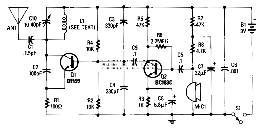
An adjustable capacitor C10 and a coil L1 create a tank circuit that, along with Q1, C2, and R1, oscillates at a frequency within the FM band. The center frequency is adjustable by tuning C10. An electret microphone, M1,...
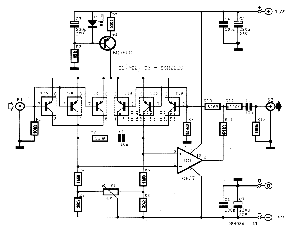
The preamplifier is designed for signal sources such as low-impedance moving coil cartridges (MC) used in high-fidelity turntables. The amplifier has an impedance of 100 ohms. To maintain low noise levels, three double-type transistors, either MAT03 or SSM2220, are...
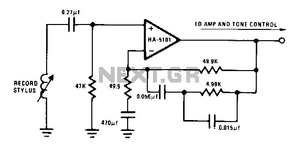
The circuit provides low-frequency boost below 318 Hz and high-frequency attenuation above 3150 Hz. Recent modifications to the response standard include a 31.5-Hz peak gain region to reduce de-oriented distortion from external vibration. The described circuit functions as an audio...
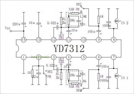
The YD9088 is a bipolar integrated circuit designed for use in mono portable and pocket radios. It is advantageous when minimizing peripheral components, which should be of small dimensions and low cost, is a priority. The circuit incorporates a...
Warning: include(partials/cookie-banner.php): Failed to open stream: Permission denied in /var/www/html/nextgr/view-circuit.php on line 713
Warning: include(): Failed opening 'partials/cookie-banner.php' for inclusion (include_path='.:/usr/share/php') in /var/www/html/nextgr/view-circuit.php on line 713