
Wireless-fm-microphone
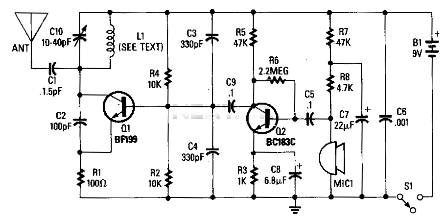
An adjustable capacitor C10 and a coil L1 create a tank circuit that, along with Q1, C2, and R1, oscillates at a frequency within the FM band. The center frequency is adjustable by tuning C10. An electret microphone, M1, captures an audio signal, which is subsequently amplified by transistor Q2. The amplified audio signal is coupled through capacitor C9 to Q1, where it frequency modulates the tank circuit. The resulting signal is then radiated from the antenna. The circuit is designed to operate within a voltage range of 9-12 VDC.
The described circuit operates as a basic FM transmitter. The tank circuit, formed by the adjustable capacitor C10 and coil L1, is crucial for determining the frequency of oscillation. The variable capacitance of C10 allows for fine-tuning of the center frequency, enabling the transmitter to be aligned with various FM radio frequencies.
The electret microphone M1 serves as the audio input source, converting sound waves into an electrical signal. This signal is weak and requires amplification, which is accomplished by transistor Q2. The amplified output from Q2 is coupled to the tank circuit through capacitor C9. This coupling is essential for frequency modulation, as it allows the audio signal to vary the oscillation frequency of the tank circuit.
Transistor Q1 functions as the oscillator, modulating the frequency of the tank circuit based on the audio signal received from Q2. The modulation process alters the frequency of the carrier wave, which is then transmitted as an FM signal. The antenna is responsible for radiating this modulated signal into the surrounding environment, allowing it to be picked up by FM receivers.
Powering the circuit within the specified 9-12 VDC range ensures proper operation of the components, particularly the transistors, which require a certain voltage to function effectively. The design of this circuit is relatively straightforward, making it suitable for educational purposes or basic radio transmission experiments. Proper tuning and alignment with an FM receiver can demonstrate the principles of frequency modulation and radio transmission.Adjustable capacitor C10, and coil L1 form a tank circuit that, in combination with Q1, C2, and R1, oscillates at a frequency on the FM band. The center frequency is set by adjusting C10. An electret microphone, M1, picks up an audio signal that is amplified by transistor Q2. The audio signal is coupled via C9 to Q1, which frequency modulates the tank circuit. The signal is then radiated from the.antenna. The circuit can operate from 9-12 Vdc. 🔗 External reference
Related Circuits

Utilize standard RF wiring precautions. Optimal speech clarity is achieved by employing an electret microphone. For music reproduction, replace it with a dynamic microphone element. In the design of audio circuits, particularly those involving speech and music, the choice of...

Transistor Q1 functions as an amplifier for the condenser microphone MIC1. The output from Q1 is fed to the base of transistor Q2 through a 4.7 µF capacitor. Capacitors C2 and L1 form an LC tank circuit, which is...