
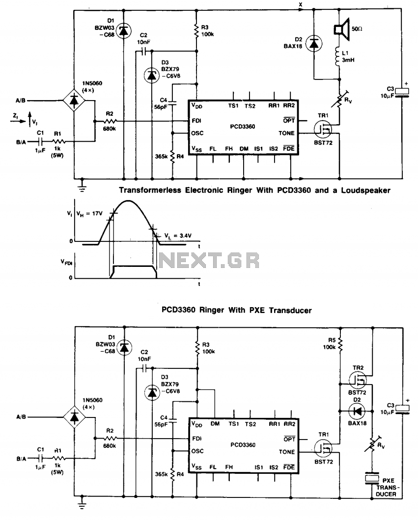
Programmable multi-tone telephone ringer
The circuit utilizes two BST72 transistors configured to amplify signals, resulting in an output voltage swing that closely matches the voltage at capacitor C3. This configuration is advantageous for applications requiring precise voltage regulation or signal amplification.
In this setup, the transistors serve as the primary amplification elements, with their collector-emitter paths connected in such a way that enhances the output voltage. The choice of the BST72 transistors is critical due to their favorable characteristics, such as high gain and fast switching capabilities, which contribute to the overall performance of the circuit.
Pins IS1 and IS2 are noted to be inoperative when the DM signal is HIGH. This indicates that the circuit has a built-in mechanism for disabling certain functions or components based on the state of the DM signal, which can be used to manage power consumption or signal routing within the circuit. The design may include additional logic to ensure that these pins are only activated under specific conditions, thereby optimizing the circuit's operation.
Volume control is facilitated by the inclusion of resistor Rv. This resistor allows for adjustable attenuation of the output signal, providing a means to control the volume in audio applications or to modulate signal strength in other contexts. The value of Rv can be selected based on the desired range of volume control, and it may be part of a potentiometer arrangement for variable adjustment.
Overall, this circuit design effectively combines transistor amplification, signal management, and user-adjustable volume control, making it suitable for various electronic applications where signal integrity and user interaction are essential.Two BST72 transistors provide an output voltage swing almost equal to the voltage at C3. Pins IS1 and IS2 are inoperative because DM = HIGH. Volume control is possible using resistor Rv. 🔗 External reference
Related Circuits
This project is designed for individuals with large homes, expansive gardens, and young children. It is a telephone ringer that enables any mains-powered device to operate in response to the ringer of a fixed-line telephone. This device can control...
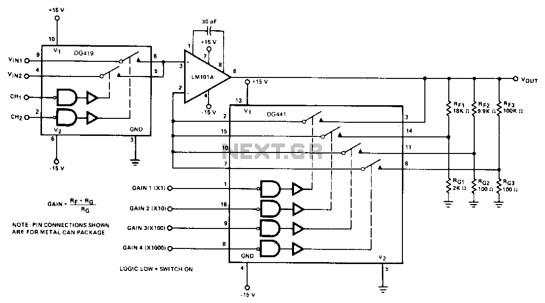
The DG419 considers the high input impedance of the operational amplifier, making the effects of Rvs negligible. The DG441 is also connected in series with RIN and is not included in the feedback dividers, thereby contributing negligible error to...
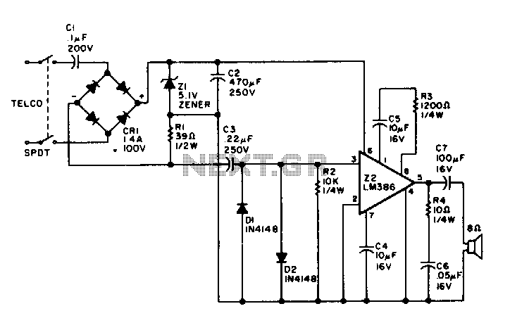
Utilizing rectified audio as a power supply, this monitor will transmit the audio from the telephone line to an 8-ohm speaker. The circuit leverages the concept of rectifying audio signals to provide a usable power supply for driving an 8-ohm...
Audio Visual Ringer. Often, there is a need for an additional telephone ringer in an adjoining room to indicate an incoming call. For instance, if the telephone is installed in a location that is not easily audible. The Audio Visual...

Air coils can be constructed at home relatively easily and are capable of oscillating at frequencies above 100 kHz, which may decrease as larger coils achieve inductance levels similar to ferrite core coils. With careful design, it is possible...

This circuit provides protection for telephones, EPABX systems, telephone modems, and similar devices against lightning discharges and line voltage spikes. It incorporates a safety capacitor and gas discharge components. The circuit employs a safety capacitor to filter out high-frequency noise...