
Telephone Ringer
It is essential to understand that the ringer voltage on a fixed telephone line is relatively high. While the exact voltage and frequency may vary by country due to the lack of regulation from the European Union Commission, this detail is not critical for this project. The telephone line carries direct current, whether it is in use or not. Only a small amount of current, typically a few hundred milliamperes, needs to be drawn from an unoccupied telephone line to simulate an occupied state for the PSTN exchange.
Capacitor C1 serves a dual purpose: it isolates the project from the direct current on the line while allowing the ringer current to pass. The ringer current is rectified by diode D1 and clipped by D2, providing approximately 6 V DC to the terminals of capacitor C2 when a ringing signal is detected. This voltage powers LED D3, which acts as a visual indicator of proper operation, along with an LED in integrated circuit IC1. IC1 is a high-power phototriac with zero-crossing detection from the mains, enabling it to switch the load without generating noise, functioning similarly to a solid-state relay.
The selected component comes in a package similar to TO220, slightly larger, with four pins. The pinout is clearly marked on the packaging to avoid confusion. This circuit is not widely available, but it can be sourced from Conrad Electronics. For safety, the circuit includes a GeMOV on the mains side, also known as a varistor, VDR, or SiOV, depending on the manufacturer. The load is limited to 2 A, which is sufficient for the intended application. Finally, due to the connection of several components directly to the mains power supply, the assembly must be housed in a fully insulated enclosure to ensure safety.
This project not only enhances the audibility of a telephone in large spaces but also provides flexibility in its application, offering both audible and visual alerts while maintaining safety standards through proper component selection and housing.If you are lucky enough to have a big house, a large garden, and small children, this project just might interest you. It`s actually a telephone ringer capable of making any mains-powered device work from the ringer of your fixed line.
With it, you will be able to control a high-powered siren or horn, as you like, in order to relay and amplify the low-level sound of your telephone (making it audible in a big house or in a large garden)! Alternatively, you can make a lamp light (or an indicator light) and so create a silent ringer` (helpful when small children are napping). The other interesting part of this simple and inexpensive project is that it doesn`t require a power supply, contrary to similar items on sales in the shops.
Before examining the drawing and understanding the principle involved, it is important to know that the ringer voltage on a fixed telephone line is pretty high. Since Europe and the EU Commission have not yet interfered, the exact value of this voltage and its frequency varies according to the country, but that`s not important here.
The line carries direct current whether unoccupied or occupied. Moreover, no more than a few hundred mAs needs to be stolen from an unoccupied telephone line to make the PSTN exchange believe the line is occupied. Therefore, capacitor C1 has the dual role of insulating this project with respect to direct current present on the line while unoccupied, or while occupied, while also allowing the ringer current to pass.
The latter is rectified by D1 and clipped by D2 which makes about 6 V DC available to the C2 terminals when a ringer signal is present. This voltage lights LED D3 which only serves as a visual indicator of proper operation as does the LED contained in IC1.
This is a high-power photo triac with zero crossing detection from the mains, which allows it to switch the load it controls without generating even the lowest level of noise. This component, that we might just as well call a solid-state relay, was selected because it is comes in the form of a package similar to a TO220, a little bigger, and equipped with four pins.
The pinout will not cause confusion because the symbols shown on our diagram are engraved or printed on the packaging. Since this circuit is not yet very common, we need to mention that it`s available from the Conrad Electronics website ( For the purpose of safe operation, the circuit is protected by a GeMOV on the mains side, called Varistor, VDR or SiOV depending on the manufacturer.
The model indicated here is generally available. The load will be limited to 2 A, considering the model selected for IC1, which is more than sufficient for the application planned here. Finally, since a number of components in this circuit are connected directly to the mains power supply, the assembly should be placed in a completely insulated housing for obvious safety reasons.
🔗 External reference
Related Circuits

Electronic FM Telephone Transmitter Schematic. The following schematic design illustrates a circuit diagram for an FM telephone transmitter built on a compact PC board layout. This small design allows it to be easily integrated within the housing of a...
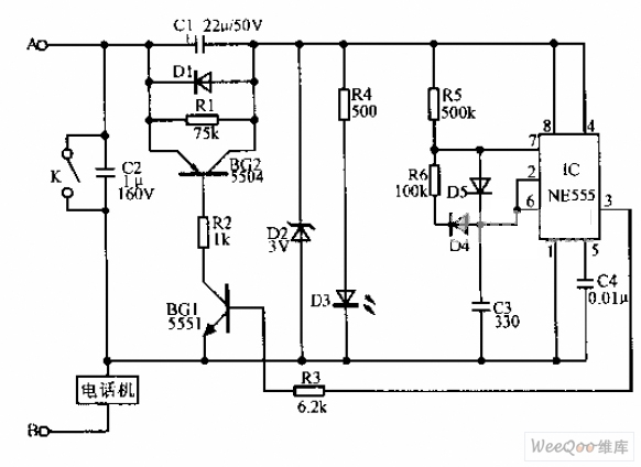
A simple telephone time lock circuit is depicted in the provided diagram. In this circuit, BG1 and BG2 function as electronic switches that are controlled by the IC NE555. When the telephone is on-hook, the DC resistance of the...
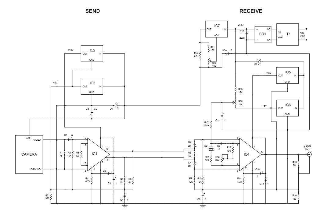
The Videowire converts a baseband video signal into a low impedance differential signal that can be sent over ordinary four conductor telephone wire. A send board mounted close to the camera generates the differential signal and a receive board...
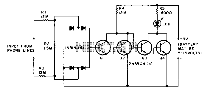
The LED flickers when the phone is ringing or being dialed. It glows steadily when the phone is off the hook. The described circuit involves an LED indicator that serves two primary functions based on the state of the phone....

The automatic alarm circuit comprises a DTMF automatic dialing system, a password control circuit, a voice detection and alarm circuit, a telephone interface circuit, a power supply circuit, and a keyboard display circuit. The automatic dial-up alarm utilizes the...
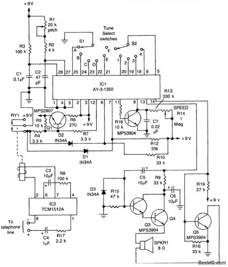
The core component of the circuit is IC1, the AY-3-1350 melody synthesizer IC from General Instrument. IC2 is a TCM1512 telephone ring detector IC powered by the telephone line. The circuit operates when IC2 detects a ring pulse on...