
Programmers in circuit serial programming
The EPIC Plus Programmer is designed to facilitate efficient in-circuit programming of various PIC Microcontrollers, ensuring that developers can program and test their devices without the need for removal from their target application. The 10-pin header J3 provides a standardized interface for connecting to the microcontroller, allowing for easy integration into existing designs.
For optimal performance, it is essential that the connections made to the microcontroller are precise and adhere to the specifications outlined in the programming diagram. The careful design of the cable length, not exceeding 150mm, minimizes signal degradation and potential programming errors, ensuring reliable communication between the programmer and the target device.
When using the programmer with different PIC Microcontrollers, it is crucial to consult the specific pin configurations for those devices. This ensures that all necessary signals, such as Vpp for programming voltage, RB6 and RB7 for data communication, and the ground connection, are correctly established.
The requirement for an external +5 Volt supply from the target system emphasizes the need for proper power management in the design. The programmer's header lines are not intended to supply power to external circuits, preventing potential overloading or damage to the programmer.
The inclusion of a ZIF socket on the LAB-X board enhances usability by allowing for easy insertion and removal of the microcontroller, reducing the risk of pin damage. Proper alignment of the microcontroller's notch with the socket is critical to ensure the device is oriented correctly, preventing programming failures.
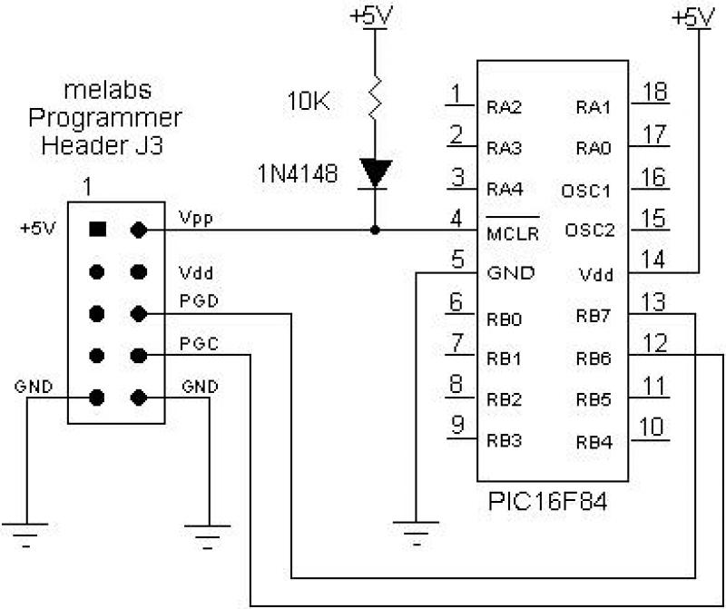
Lastly, the operational indicators, such as the LED status light, provide immediate feedback on the programmer's connection and operational state, enhancing the user experience by indicating when programming is actively taking place. This feature is particularly useful for debugging and ensuring that the programming process is proceeding as intended.The EPIC Plus Programmer, Serial Programmer, USB Programmer or U2 USB Programmer may be used for in-circuit serial programming of serially programmable PIC Microcontrollers through the 10-pin expansion header J3. Vpp, RB6, RB7 and ground should be connected as in the following diagram. Any additional connections to /MCLR, RB6 and RB7 should be d
esigned as to not interfere with in-circuit programming. The cable connecting the programmer ’s 10-pin header to the target board should be less that 150mm in length. The drawing shows the pinouts and connections to the 18-pin PIC16F84. For other PIC Microcontrollers, use their corresponding pin connections. Note: +5 Volts should be supplied to the PIC Microcontroller by the target system. The +5 Volt and Vdd lines from the programmer header are not intended to power external circuits. Note for PIC17C7xx: These devices may also be programmed in-circuit. However, different pins are required than shown above. See the Microchip programming spec on these devices for more information. Connect your programmer to the LAB-X board using a 10-pin Header Cable. Do not twist or fold the cable to make the connection. The connectors on the programmer and LAB-X boards should line up to allow a straight connection. If your LAB-X board has a ZIF socket, raise the lever. Insert the microcontroller into the socket on the LAB-X board and lower the lever to lock it into place.
Make sure that the notch on the end of the microcontroller is aligned with the lever end of the socket. If your LAB-X board does not have a ZIF socket, carefully line up the PIC Microcontroller ’s pins with the holes in the socket and press it into place.
Make sure the notch on the end of the microcontroller is aligned with the notch at the end of the socket. Connect a suitable AC Adapter to the programmer ’s power jack. You may have different adapters for the programmer and LAB-X board. Make sure you power the programmer with the correct adapter. The LED indicator on the EPIC Plus Programmer will remain lit at half intensity when connected to the LAB-X board.
The indicator should light fully when a programming operation is in progress.
Related Circuits

Circuit characteristics: A simple phase shift range of 180 degrees, with a practical range of 170 degrees. The circuit is influenced by temperature and is suitable for small power applications in less demanding situations. The circuit operates by utilizing a...

The lighting controller depicted in the figure features a gradual dimming function that prevents sudden brightness changes, which can irritate the human eye and potentially cause damage due to inrush currents. The circuit design includes a six-stage CD4069 inverter...

This design circuit is for a temperature sensor that utilizes an LM335 integrated circuit (IC) to convert ambient temperature into an equivalent output voltage. The output voltage of the LM335 increases by approximately 10 mV for every 1 degree...
This is a low-cost FM antenna booster designed to enhance reception of programs from distant FM stations. The FM antenna booster circuit features a common-emitter tuned RF preamplifier utilizing the VHF/UHF transistor 2SC2570 (C2570). The schematic illustrates the configuration...

A bidirectional H-bridge DC motor control circuit is illustrated. The circuit utilizes the L298 integrated circuit from ST Microelectronics. The L298 is a dual full-bridge driver that supports a wide operating voltage range and can manage load currents up...
The following circuit illustrates the use of a 555 integrated circuit (IC) for an infrared (IR) remote control extender circuit. Features include support for 850 nm and 950 nm signal wavelengths, along with the capability to generate control pulses. The...