
Proximity Detector Circuit
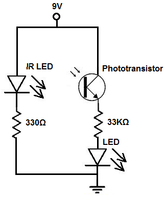
The proximity detector circuit operates based on the principles of infrared light transmission and reception. The IR LED emits infrared light, which is typically invisible to the human eye but can be detected by the phototransistor. The choice of components is crucial for the circuit's performance. The IR LED should be selected based on its wavelength and intensity, ensuring optimal detection range. The phototransistor should have a suitable spectral sensitivity that matches the wavelength of the emitted infrared light.
In the angled configuration, the IR LED and phototransistor should be positioned to maximize the detection area while minimizing interference from ambient light sources. It is important to ensure that the angle of the phototransistor allows for adequate reflection of the infrared light from nearby objects. This setup allows the circuit to detect the presence of objects within a certain proximity, triggering the output device, such as an LED or buzzer, to indicate the detection event.
For practical applications, the output component can be chosen based on the specific requirements of the project. The use of a red LED provides a clear visual indication of detection, while a green LED or buzzer could serve different signaling purposes. The circuit can be powered using a low-voltage power supply, ensuring safe operation and compatibility with various output devices.
In summary, the design of the proximity detector circuit relies on the effective alignment and configuration of the IR LED and phototransistor, as well as the selection of appropriate output components to achieve the desired functionality.There are 2 ways to build a protximity detector. One is mount the IR LED and the phototransistor so that they face each other. Then the infrared light is detected by the phototransistor. If an object comes between the IR LED and the phototransistor, the light is blocked, and the phototransistor turns off. The other way is to build a proximity dete ctor is to mount the IR LED and the IR photodiode next to each other facing the same direction. When an object comes near the IR LED, some infrared light will bounce off the object and be detected by the phototransistor. Although it can`t be seen from the schematic, this circuit assumes that the IR LED and the phototranssitor are oriented so that the phototransistor can detect the infrared light emitted by the IR LED.
This can be either indirectly (for a proximity detector) or directly (for an interrupter). Since we are building a proximity detector circuit, they should be oriented so that they are at an angle to each other. This way, when an object or a person (a human body) comes in front of the IR LED and the phototransistor, some of the infrared light will bounce off the person or object and be detected by the phototransistor.
Once the phototransistor detects this infrared light, it will conduct electricity and turn on the red LED. You can see how the IR LED and phototransistor should be placed at an angle to each other so that the phototransistor can detect the infrared light if a person or object comes into proximity.
If the IR LED and the phototransistor are directly facing each other, the circuit would be an interrupter. The red LED would normally be on. This is because the IR LED would always be beaming infrared light directly on the phototransistor. As a result, the phototransistor would always be conducting electricity, having the red LED continuously on.
when a person now steps in between these two objects, the phototransistor would no longer detect the LED and the red LED would shut off. Even though we used a red LED for this project, you can substitute it for anything. You can use a green LED. You can use a low-voltage buzzer. You can use any component which you`d like to replace it, as to how you want you want to be powered when the transistor detects infrared light.
🔗 External reference
Related Circuits

The circuit is capable of driving the company's Dialight 745-0005 monitor, which features a 64-character alphanumeric display. It generates 0-second and 1-second input signals on lines A1 through A6 based on the phase response of the desired characters, utilizing...

Metal detectors can be categorized based on their operational principles into three types: BFO (Beat Frequency Oscillator), TR/IB (Transmit-Induction/Balance), and PI (Pulsed Induction). Each method has its own set of advantages and disadvantages. An ideal metal detector, which does...
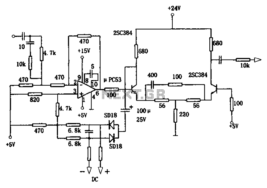
The circuit is designed for a broadband linear detection application with a bandwidth of 10 MHz. It serves as a millivoltmeter measuring instrument suitable for frequencies exceeding 10 MHz. The circuit features a linear detector utilizing operational amplifiers, specifically...

This flash circuit is a typical camera flash. This flash circuit functions as a high-voltage power supply for camera flash units, enabling the rapid discharge of energy to produce a bright flash of light. The primary components of a typical...
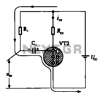
When VRI is off, 0 [2 is activated, allowing current to flow through RJ and Ci. When VT1 conducts, charging of C1 begins, causing it to discharge. This results in an inverting charge on C1, making the voltage positive,...

Figure aa, bb, and ce represent three-phase windings. A double throw switch Kl-1 to Kl-4 is positioned on the left side, connecting phases 1 and 2. At this point, aa and bb are in series with the secondary of...
Warning: include(partials/cookie-banner.php): Failed to open stream: Permission denied in /var/www/html/nextgr/view-circuit.php on line 713
Warning: include(): Failed opening 'partials/cookie-banner.php' for inclusion (include_path='.:/usr/share/php') in /var/www/html/nextgr/view-circuit.php on line 713