
pseudo track occupancy detector

The track occupancy detector circuit is designed to provide reliable feedback for model train operations, particularly in scenarios where visibility is limited. The use of diodes allows for effective current sensing while minimizing the impact on locomotive performance. The choice of 1N4001 diodes is appropriate due to their robustness and suitability for handling the required current levels. The design's compatibility with various Märklin track types enhances its versatility, making it an ideal choice for hobbyists looking to upgrade their existing setups without extensive modifications.
The integration of an opto-coupler offers additional flexibility, allowing for interfacing with digital detection systems, such as the s88 module, which can expand the functionality of the circuit. This adaptation enables users to incorporate the occupancy detection into larger control systems, enhancing automation and monitoring capabilities for model train layouts. The flickering behavior of the LEDs can also serve as a visual indicator for troubleshooting and operational awareness, providing real-time feedback on track occupancy and vehicle presence.
In summary, this track occupancy detector circuit provides a practical and efficient solution for model train enthusiasts, offering easy installation, compatibility with existing systems, and the potential for integration with advanced digital control modules.Track occupancy detectors are needed for hidden yards and other sections of track that are hard to see, but they are also necessary for block operation. The circuit described here uses an LED to indicate track occupancy for digitally controlled MG¤rklin HO model train systems (including Delta Control).
In contrast to a real track occupancy detecto r, which detects all vehicles, it only responds to vehicles that draw traction current. This means it can be used without making complicated modifications to the rolling stock and track, since it is only necessary to gap the third rail. This circuit is thus especially suitable for retrofitting to existing installations, and it is equally well suited to M, K and C tracks.
The basic idea of the circuit is simple. If a locomotive enters the monitored track section, a current flows through the motor. This current is sensed and generates an indication. With a MG¤rklin Digital system, power is provided to the locomotive via a controller or a booster in the form of a square-wave voltage. The voltage levels on the rails are approximately 15 V and +15 V. Digital control information is transferred by a continuous sequence of alternating plus and minus levels.
This means that the detector circuit must be able to respond to AC signals. In Figure 1, the monitored track section on the left is connected to the ground terminal 0` via the rails. The third rail, with conducts the traction current to the locomotive, is isolated from the rest of the system (special third-rail insulators are available for this purpose), and it is connected to the B` terminal of the controller or booster via the detector circuit.
If a locomotive travels over the monitored track section, the positive component of the drive current flows through diodes D1 and D2, while the negative component flows through D3. With a motor current of approximately 250 mA, the voltage drop across a single diode (1N4001 types are used here) is a good 1 V.
The voltage drop across the two diodes connected in series (D1 and D2) is sufficient to illuminate LED1. Although the locomotive will travel somewhat slower due to the voltage drop, this will not cause any problems.
A second detector can be obtained by connecting an additional diode to the circuit as shown in Figure 2. This causes a second LED to illuminate for negative drive current. Due to the pulse trains and fluctuations in the traction current, the LED illumination is not constant, but instead flickers more or less strongly.
Other traction-power loads, such as coach lighting or taillights, will also generate an occupied` indication. In such cases, the LED will remain illuminated even if the locomotive is standing still with no current flowing through the motor.
Sometimes the quiescent current through a decoder is sufficient to cause the LED to illuminate (a little bit) even if the locomotive is standing still. Another possibility is to use an opto-coupler instead of an LED. This would allow the circuit to be connected to an s88 detection module. 🔗 External reference
Related Circuits
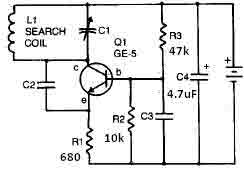
This metal detector circuit needs to be powered using a 9 volts power supply (DC) or a 9 volts battery. The C1 capacitor is a variable capacitor with a value of 365 pF, C2 is a 100 pF silver...
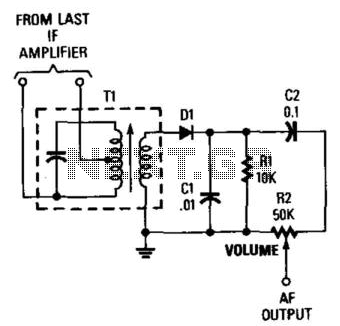
This general-purpose detector for AM envelope detection can be used in various receiver applications. T1 matches the IF amplifier impedance (typically 1 to 10 kΩ) to the approximately 1 kΩ detector impedance. D1 can be an IN60, IN82AG, IN270,...

I decided to make a commercial surface mount PC board using the LED2 sensor concept. It is quite sensitive and can track to a few degrees of accuracy in bright sunlight. If a blocking shadow is used the accuracy...

This project involves the design of an embedded system for tracking and positioning vehicles using the Global Positioning System (GPS) and the Global System for Mobile Communications (GSM). When a user sends a request to the number associated with...
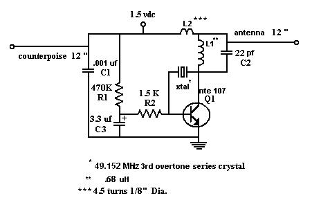
The M15m Tracking Transmitter is a modified version of the M15 Animal Tracking Transmitter. It has been designed to operate on 147.460 MHz using an inexpensive 49.152 MHz computer crystal and is intended for printed circuit board construction. The...

The circuit utilizes a precision integrated temperature sensor, the LM35 (IC1), which provides a linear and directly proportional output in millivolts over a temperature range of 0 to +155 degrees Celsius. This sensor can be incorporated into fire smoke...