
Small Metal detector schematic circuit
The metal detector circuit operates on a simple principle of frequency modulation, utilizing a combination of capacitors, inductors, and a transistor to detect changes in the electromagnetic field caused by nearby metallic objects. The circuit is powered by a 9-volt DC supply, which can be sourced from either a battery or an external power supply.
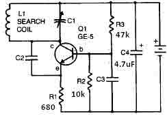
The variable capacitor, C1, has a capacitance range of up to 365 pF, allowing for fine-tuning of the oscillator frequency. This is crucial for achieving the desired detection sensitivity. The fixed capacitors, C2, C3, and C4, serve specific roles in the circuit. C2, a 100 pF silver mica capacitor, is typically used for stability in high-frequency applications, while C3, a 0.05 uF disc capacitor, may be used for coupling or bypassing, ensuring that unwanted frequencies do not affect the circuit's operation. C4, with a capacitance of 4.7 uF, is likely employed for power supply filtering, smoothing out any voltage fluctuations that could interfere with the circuit's performance.
The transistor Q1, an RCA SK3011 or an equivalent NPN type, acts as an amplifier and is essential for processing the signals generated by the oscillator. The choice of a ½-watt resistor rating throughout the circuit ensures that the components can handle the power levels without overheating, contributing to the circuit's reliability.
The L1 coil, which is a critical component of the metal detector, consists of 18 turns of 0.65 mm enameled wire wound on a 4-inch diameter form. This coil acts as an inductor and is responsible for generating the electromagnetic field. When a metallic object enters this field, the inductance of the coil changes, which in turn alters the frequency of the oscillator. This frequency shift produces a beat tone in the radio receiver, indicating the presence of metal.
The overall design of this metal detector circuit is straightforward, making it suitable for hobbyists and educational purposes, while also demonstrating fundamental electronic principles such as resonance, oscillation, and signal detection.This metal detector circuit needs to be powered using a 9 volts power supply ( DC) or a 9 volts battery . The C1 capacitor is a variable capacitor with a value of 365 pF , C2 is a 100pF silver mica capacitor , C3 is a 0.05 uF disc capacitor and the C4 is a 4.7 uF capacitor .
The Q1 transistor can be RCA SK3011 npn transistor or equivalent type and all resistors need to be ½ watts . This metal detector schematic circuit is based on a transistor radio as an detector . With the radio tuned to a weak station you must adjust the variable capacitor C1 until the locator oscillator beats against the received signal . If a metal is detected the inductance of the L1 coil is changed , changing the frequency of the locator oscillators , resulting a change in the beat tone radio .
The L1 search coil of the metal detector circuit must have 18 turns from a 0.65 mm enameled wire scrambled on a 4 inch diameter support . 🔗 External reference
Related Circuits
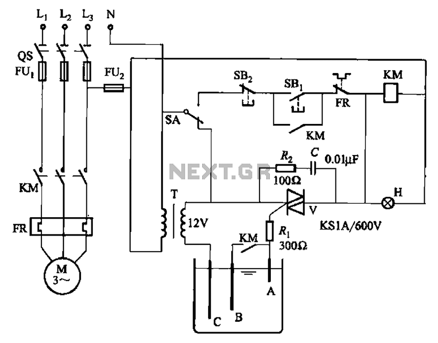
Bidirectional thyristor control manages the trigger voltage output from the step-down transformer at 12V when the water activates the electrodes. It is part of a drawable circuit that regulates the level. The circuit includes a current-limiting resistor (Ri) to...
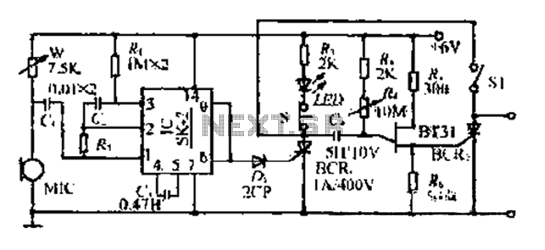
The circuit includes a microphone (MIC) housed in a cylindrical body that captures sound when an object makes contact. The audio signal is coupled to an integrated circuit (IC) for amplification. The output from the IC, at pins 6...
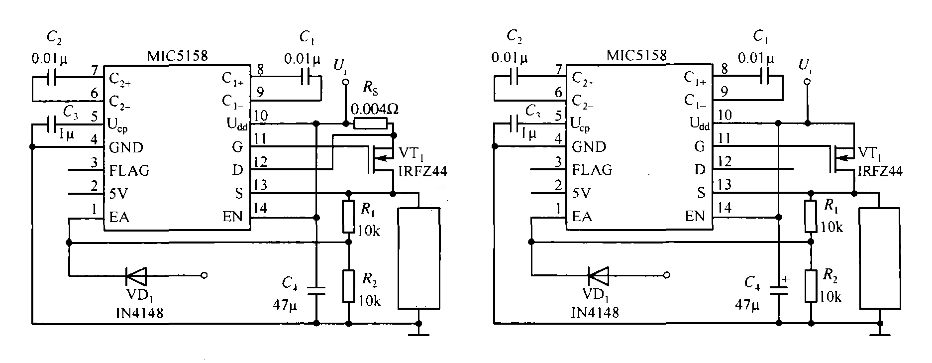
The MIC5158 is part of a high-speed switching circuit diagram that focuses on the rising edge. The MIC5158 is a precision voltage reference and high-speed switching device that is commonly utilized in various electronic applications requiring rapid signal transitions. In...
To enhance usability during nighttime, the receiver features a scale with bias lighting, and the surface behind the scale is coated with a fluorescent material. To activate the scale illumination, press button 3. Radio programs can be listened to...
This circuit is designed to demonstrate high frequency and high voltage, capable of producing approximately 30kV, depending on the transformer utilized. It is cost-effective and straightforward to construct, primarily using a standard TV flyback transformer. This circuit can power...
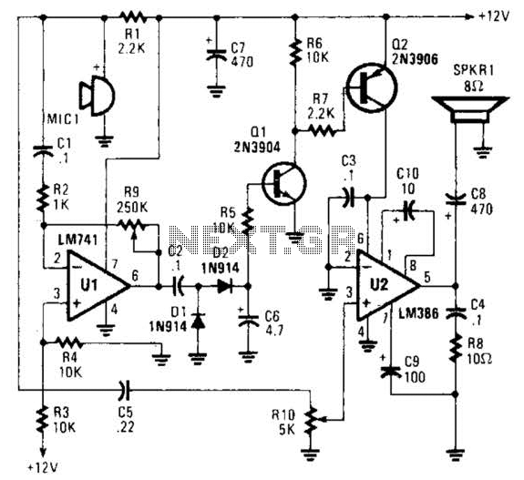
An omnidirectional electret microphone is utilized to capture sound and convert it into an electrical signal. The output from the microphone is directed along two pathways. In the first pathway, the signal is routed to the inverting input at pin...
Warning: include(partials/cookie-banner.php): Failed to open stream: Permission denied in /var/www/html/nextgr/view-circuit.php on line 713
Warning: include(): Failed opening 'partials/cookie-banner.php' for inclusion (include_path='.:/usr/share/php') in /var/www/html/nextgr/view-circuit.php on line 713