
Pulse-Generator & Signal-Tracer

The described circuit functions as a pulse generator, specifically designed to produce narrow pulses at a frequency range of 700-800 Hz. This frequency is suitable for various testing applications in audio and radio-frequency domains. The output pulses are rich in harmonics, extending into the MHz range, which enhances the circuit's capability to stimulate various stages of amplifiers and receivers effectively.
The circuit typically utilizes a timer IC, such as the 555 timer, configured in astable mode to generate the desired pulse frequency. The frequency can be adjusted by varying the resistor and capacitor values connected to the timer. The output pin of the timer drives a transistor or a MOSFET to amplify the pulse signal, ensuring that it can adequately drive the input stages of the device under test.
For testing, a clip is used to connect the circuit to the ground of the device under test, providing a common reference point. The probe is then used to inject the pulse signal into different stages of the circuit, starting from the output stage and moving towards the input stage. This method allows for systematic testing and troubleshooting of the device, as any deviation in expected performance can be traced back through the circuit stages.
When the circuit operates correctly, a high-pitched tone is audible from the speaker of the device under test, indicating that the injected pulses are being processed correctly. This feedback is crucial for verifying the integrity of the circuit under test and ensuring that it is functioning as intended. Proper precautions should be taken to ensure that the circuit does not exceed the input ratings of the device under test to avoid damage.This simple circuit generates narrow pulses at about 700-800Hz frequency. The pulses, containing harmonics up to the MHz region, can be injected into audio or radio-frequency stages of amplifiers, receivers and the like for testing purposes. A high-pitched tone can be heard from the speaker of the device under test when all is working properly.
The clip must be connected to the ground of the device under test, touching with the probe the different stages of the circuit, starting from the last stage and going up towards the first. 🔗 External reference
Related Circuits
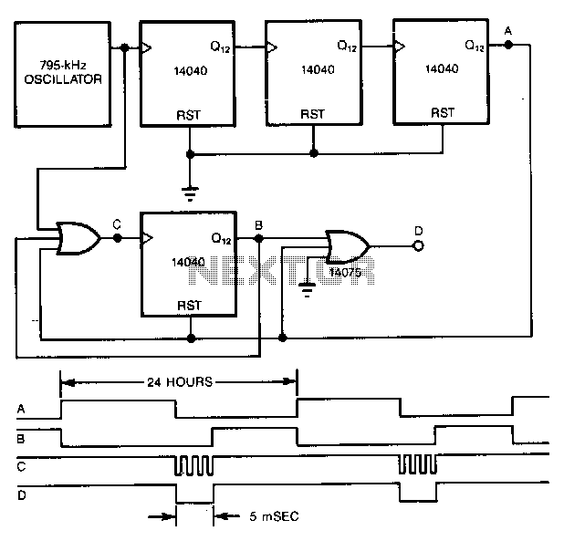
A precise pulse generator can be constructed using a precision oscillator and several CMOS counters. The number of counters can be increased to extend the pulse period as needed. This circuit will generate a pulse approximately 5 ms long...
There have been a lot of transistor tester circuits in recent electronics magazines, but this one is different. It has more features and includes a signal injector so you can test audio sections of radios and the front end...
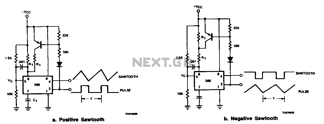
The output at pin 3 of the 566 can be utilized to deliver varying charge and discharge currents for capacitor Cl, resulting in a sawtooth waveform available at pin 4 and a pulse output at pin 3. It is...
Since the output buffer of P1 can sink 20mA (each output pin, but maximum IOL for all outputs was limited at 80mA), thus we can use P1 to drive LED display directly. As shown in the circuit, Two common-anode...
Built around an LM380, this amplifier includes tone controls and electronic "soft switching". The soft switching circuitry ensures power is built up gradually eliminating the dc thump. The soft switching is enabled by a BD131 transistor wired as a...
This circuit is permanently plugged into a mains socket and NI-CD batteries are trickle-charged. When a power outage occurs, the lamp automatically illuminates. Instead of illuminating a lamp, an alarm sounder can be chosen. When power supply is restored,...