
TRANSISTOR TESTER & SIGNAL INJECTOR
This transistor tester circuit is designed to enhance the functionality and usability of traditional transistor testing methods. It incorporates a signal injector, allowing the user to test not only the transistors themselves but also audio sections of radios and the front end of FM transmitters. This dual capability makes it a versatile tool for electronics enthusiasts and professionals alike.
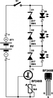
The circuit operates automatically, which significantly simplifies the testing process. Users can connect the three leads of a transistor—emitter, base, and collector—in any order, eliminating the confusion often associated with identifying lead configuration. The circuit utilizes a series of light-emitting diodes (LEDs) to provide immediate visual feedback. These LEDs indicate the base lead of the transistor and identify whether the transistor is of the NPN or PNP type.
The design may include a microcontroller or dedicated logic circuitry that interprets the connections and controls the LED indicators. The signal injector functionality can be implemented using a simple oscillator circuit that generates a test signal, allowing the user to assess the performance of the transistor in real-world applications, such as audio amplification.
In terms of component selection, the circuit may utilize standard discrete components such as resistors, capacitors, and transistors, making it accessible for hobbyists to build. The inclusion of a power supply section, likely with a voltage regulator, ensures that the tester operates reliably across a range of input voltages.
Overall, this transistor tester circuit represents an advancement in testing technology, combining ease of use with expanded functionality, making it a valuable addition to any electronics toolkit.There have been a lot of transistor tester circuits in recent electronics magazines, but this one is different. It has more features and includes a signal injector so you can test audio sections of radios and the front end of FM transmitters etc.
The major advantage with this design is its automatic operation. All you have to do is fit the three leads of a transistor to the tester in any order and the LEDs will let you know the base and if the transistor is NPN or PNP. 🔗 External reference
Related Circuits
These small electronic lamps are incredibly useful and have a remarkably long lifespan. Approximately 40 years after Nick Holonyak developed the first LED, they have become essential components in various applications. Any dedicated electronics hobbyist typically keeps a selection...
Field-effect transistors (FETs) are integral components found in various applications such as power sections, LCD inverters, uninterruptible power supplies (UPS), amplifiers, monitor B+ circuits, and ATX power supplies. When a FET fails, it is essential to use a meter...
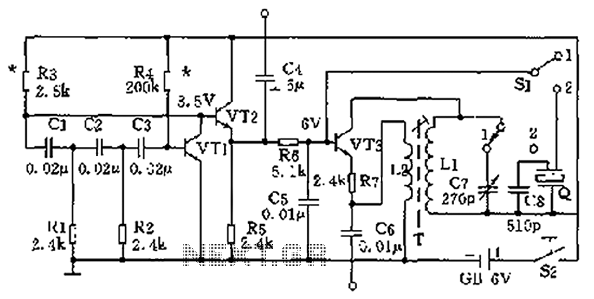
The high-frequency signal generator is designed to produce a low frequency of 1 kHz, an intermediate frequency (IF) signal of 465 kHz, and high frequencies ranging from 525 kHz to 1605 kHz. This device is particularly useful for radio...
Read the generic sound level from an electret microphone. Several schematics utilize NPN transistors that yield an inverted output (~5V when quiet, ~0V when loud, with linear operation in between). However, a non-inverted output is desired, where a super...

The circuit diagram represents a useful tool for quickly testing various types of thyristors, including silicon-controlled rectifiers (SCRs) and triacs. For triacs, all four quadrants are assessed using switch S3, while testing a standard thyristor requires the adjustment of...
The following circuit illustrates a BC547 transistor used in an output relay delay audio amplifier circuit diagram. Features include the immediate disconnection of the speaker when the... The BC547 transistor is a widely utilized NPN bipolar junction transistor, often employed...