
Pulsed Sensor Extends Battery Life
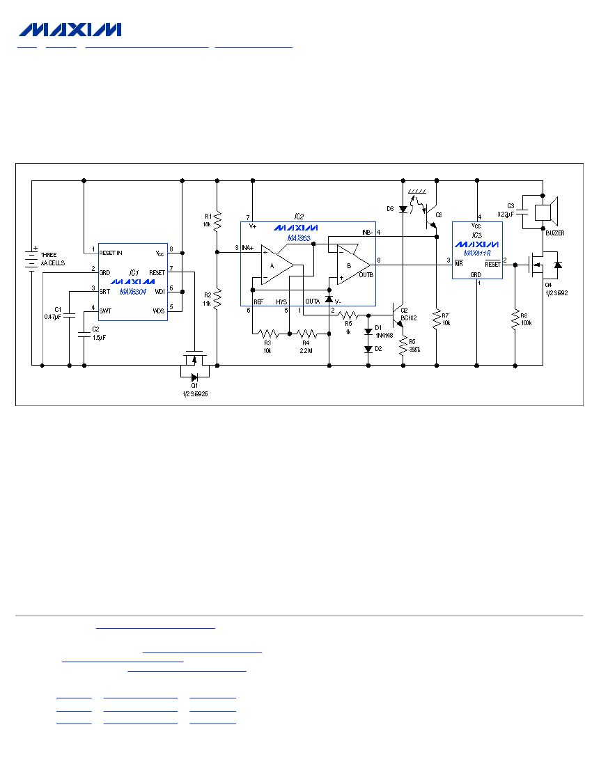
The power-saving circuit operates by employing a microprocessor supervisor (IC1) to manage the timing and power supply to the sensor system. The core of the design is the optocoupler, which utilizes an infrared-emitting diode to detect the presence of salt crystals in the water softener. This detection mechanism relies on the reflection of infrared light off the salt crystals, allowing for the determination of salt levels based on the emitter current in the phototransistor (Q3).
When the salt level falls below a predetermined threshold, the current in the phototransistor drops, and the voltage across resistor R7 reaches the reference voltage set in comparator IC2. This triggers Comparator B, which subsequently activates the manual reset for the voltage monitor (IC3). The system incorporates a delay mechanism, ensuring that any transient fluctuations in salt levels do not trigger unnecessary alarms; thus, a reset delay of 140 ms is implemented before Q4 activates the buzzer.
Battery monitoring is accomplished through Comparator A, which assesses the voltage across resistors R1 and R2. If the battery voltage exceeds 3V, it enables the infrared-emitting diode (D3) by engaging Q2, which serves as a constant-current sink. This design ensures that the sensor only receives power when necessary, thereby conserving energy.
The timing function is handled by IC1, which is configured to operate more efficiently than traditional timer circuits such as the 555 timer. By utilizing a smaller capacitor (C2 = 1.5 µF), the internal watchdog timer can achieve a timeout of 3.6 seconds. The addition of a high signal to the WDS pin extends this timeout to 30 minutes, allowing the sensor to pulse only once every half hour. Each timeout generates a reset pulse that energizes the circuit, maintaining operational efficiency while minimizing power consumption. This design approach is particularly advantageous in applications where battery life is critical, such as remote monitoring systems for water softeners.The following demonstrates a power saving circuit that pulses a Sensor for 1 second every 30 minutes. Designed to monitor levels of salt The Sensor shown is an Optocoupler with an infrared-emitting Diode Designed to monitor the level of salt Crystals in a water softener, it relies on a reflection from the Crystals to gen
erate a "no-alarm" level of emitter current in the Phototransistor (Q3). As the salt level drops past the sensor`s position, this current level makes When the drop across R7 equals the reference voltage in the Comparator reference device (IC2), Comparator B`s output goes high and releases the manual reset on the voltage monitor (IC3). After a minimum reset-delay interval of 140ms, Q4 turns on and sounds the buzzer. Comparator A monitors the Battery voltage via R1 and R2; at levels above 3V, it activates the IR-emitting Diode (D3) by turning on the constant-current sink consisting of Q2 and associated components.
Thus, the Power for the Sensor is available only when Q1 turns on. Q1 is controlled by IC1 ”a microprocessor supervisor configured as a time-base generator. (IC1 consumes less power and has a smaller footprint than the alternative 5556 Timer or a 555 Timer with multistage Counters It also eliminates the large Capacitors otherwise IC1`s external connections cause its internal watch-dog Timer to cycle repeatedly. With C2 = 1. 5 µF as shown, the internal timeout is 3. 6 seconds, and connecting WDS high multiplies this value by 500, extending it to the desired 30 minutes.
Each timeout produces a reset pulse that applies power to the remaining circuitry by 🔗 External reference
Related Circuits
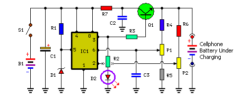
Stops charging when the battery is fully charged. Portable unit for charging mobile phones. Cellphone battery management is a significant issue while traveling, as power supply can be limited. The described circuit functions as an intelligent battery charger designed to...
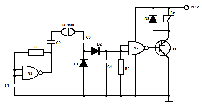
This is a straightforward liquid detector that utilizes a relay to activate an evacuation mechanism. It can be employed for water or any liquid that conducts electricity. Any PNP transistor capable of handling the relay current can be used....
The LinkSwitch-LP family is designed to replace inefficient line frequency linear transformer-based power supplies with output powers less than 2.5 W in applications such as cell/cordless phones, PDAs, digital cameras, and portable audio players. LinkSwitch-LP may also be used...
The following circuit illustrates a fully linear diode sensor circuit diagram. This circuit is based on the A748 integrated circuit (IC). Features include the use of an operational amplifier (op-amp). The fully linear diode sensor circuit utilizes the A748 IC...
This ultrasonic anemometer is designed for the two-dimensional measurement of horizontal wind speed components and wind direction, as well as virtual temperature. Due to its high measurement rate, the device effectively captures gusts and peak values without delay. The...
Camping today often requires various electronic devices for daily activities and entertainment. Typically, a charged lead-acid battery and a power inverter are utilized to ensure a well-organized trip, allowing family members to enjoy their electronic equipment. It is essential...