
Car and Motorcycle Battery Tester
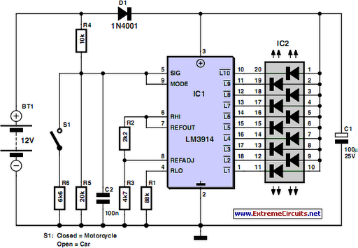
This circuit is designed to provide a straightforward and efficient method for monitoring the voltage levels of lead-acid batteries commonly used in camping and motorcycle applications. The LM3914 integrated circuit serves as the core component, which is a voltage level indicator that can drive multiple LEDs to visually represent the battery's state of charge. The circuit configuration includes a power supply section that connects to the battery being tested, either a 12V or 6V, depending on the switch position.
The use of switch S1 allows the user to easily toggle between battery types, ensuring accurate readings. When the circuit is powered on, the LM3914 receives the battery voltage and lights up the corresponding LEDs based on the voltage level detected. The top LED activation indicates that the battery is fully charged, which is an essential feature for users who rely on these batteries for their electronic devices during camping trips.
The inclusion of diode D1 is crucial for protecting the circuit from potential reverse voltage situations, which could damage the LM3914. This precaution ensures the longevity and reliability of the circuit during its use. The option to implement a color-coded display with individual LEDs provides a more intuitive way to assess battery status, as users can quickly identify the battery condition at a glance.
Overall, this circuit provides a practical solution for campers and motorcyclists to monitor their battery levels effectively, ensuring that they can enjoy their electronic devices without the worry of battery depletion. Its simplicity and low power consumption make it an ideal companion for outdoor adventures.Going camping nowadays involves taking lots of electronic equipment whether for day to day running or for fun and entertainment. Most of the time a charged lead acid battery and a power inverter would be used to ensure a smoothly organized holiday where ideally the missus and the children cheerfully use their electric and electronic gear!
With rec hargeable lead-acid batteries it`s invariably useful - if not essential - to determine whether the power source you`re hauling along on your travels is losing capacity and needs to be topped up. The same circuit would also come in handy when going on a car or motorbike trip as it can check the status of a 12 V (car) or a 6 V (motorcycle) battery.
Although the circuit draws so little power that it will not noticeably load the battery under test, it should not be left connected permanently. The circuit employs the familiar LM3914 (IC1) to display the voltage level. The LED readout creates a battery status readout: when the top LED lights, the battery is fully charged.
When the bottom LED lights, the battery needs imminent charging! Switch S1 selects between 12 V and 6 V operation. A series diode, D1, protects the bargraph driver from reverse supply voltage. A color-coded display with individual LEDs could be used instead of the common-anode bargraph display for better indication of the state of the battery. 🔗 External reference
Related Circuits
This simple circuit tests speakers, microphones, transformers, and voltage. It is essentially a very low-frequency oscillator that produces extremely short pulses. The sound produced is easy to hear and helps determine the precise direction it originates from, making it...
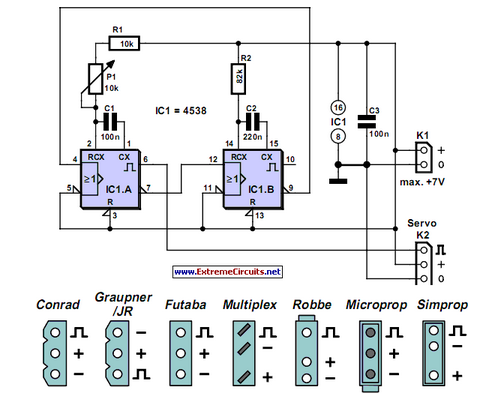
Individuals who frequently work with servos are likely familiar with situations where a servo tester is beneficial. The primary function of a servo tester is to produce a pulsing signal with a variable positive pulse width ranging from 1...

While owning a modern NiCd battery charger is advantageous, there may still be instances where an incompatible battery is encountered, such as one with an unusual voltage requirement or a need for a higher charging current than what a...
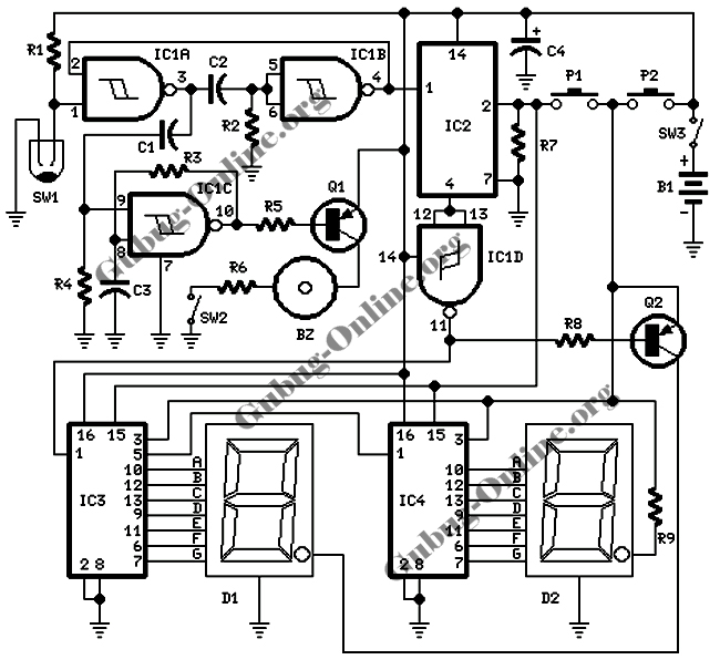
This design features a signal logic tester that utilizes a common cathode seven-segment display. The display indicates a logic level "1" (represented by an "H" on the display) or a logic level "0" (represented by an "L" on the...
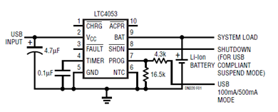
The schematic presented illustrates a minimal component solution for a USB battery charger utilizing the LTC4053 integrated circuit (IC) to create a fully compliant USB charger. This IC functions as a standalone linear charger designed for lithium-ion (Li-ion) batteries,...
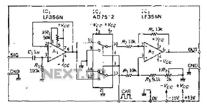
An analog switch (double loop, double-break) and a differential modulation amplifier are used in this circuit. The carrier control switch operates by switching contacts at specific times, inverting the input modulation wave. When the next carrier signal is applied...