
PWM Control Dimming Halogen Lamp
The PWM (Pulse Width Modulation) control dimming circuit is designed to regulate the brightness of a halogen lamp effectively. It operates by varying the duty cycle of the PWM signal, which controls the average power delivered to the lamp. The circuit typically consists of a microcontroller or a dedicated PWM controller, a power MOSFET, and a transformer.
In this setup, the power transformer steps down the high voltage AC supply to a safe low voltage AC level suitable for the halogen lamp. The PWM controller generates a square wave signal that modulates the power MOSFET. By adjusting the width of the pulses, the controller can alter the average voltage and current reaching the lamp, thereby controlling its brightness.
The circuit may also include additional components such as diodes for rectification, capacitors for filtering, and resistors for setting the PWM frequency. A heat sink may be necessary for the power MOSFET to dissipate heat generated during operation.
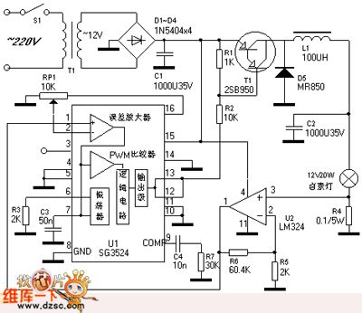
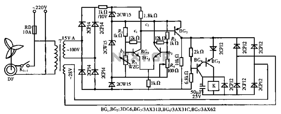
This dimming method is efficient, as it reduces power waste compared to traditional resistive dimmers. The PWM dimmer can provide smooth transitions in brightness without flickering, making it suitable for various lighting applications. Safety features such as overcurrent protection and thermal shutdown may also be integrated to ensure reliable operation and longevity of the components involved.The PWM control dimming halogen lamp circuit is as shown. Rated voltage of the halogen lamp is 12V, the nominal power is 20W, the dimmer circuit can adjust the intensity of halogen lamp from zero to maximum. Lighting halogen lamp always transforms the frequency electricity (220V or 110V) into 12V AC voltage by using the power transformer.
In order to provid.. 🔗 External reference
Related Circuits

To create a PWM controller, begin with a sawtooth generator powered by a 7.5V regulated supply to achieve a Vpp of 5V. Connect the sawtooth output to one input of a comparator and the MAP voltage to the other...
To sense and control the current in stepping motors and other similar devices, a linear integrated circuit such as the L6506 can be utilized. This chip set enables the formation of a constant current output. The L6506 is a versatile...
The NE570 can be used to make a high performance compressor FTA, except that the rectifier is connected to the input. This makes gain inversely proportional to the input level so that a drop of 20 dB input level...
The circuit is capable of enhancing the system power factor to a value exceeding 0.99. It effectively reduces the waveform distortion of the input supply current, ensuring compliance with GB15144 standards, with a distortion index lower than level L....
The 555 IC is configured as an astable multivibrator, producing a constant frequency independent of the duty cycle. The total resistance (R_charge + R_discharge, with the diode in consideration) remains constant at 22 kΩ, resulting in a frequency of...
The circuit is a bistable circuit where each bistable unit is controlled by high and low output levels. When power is supplied to the circuit, current flows through components R13, CL, and VD to VD2 for full-wave rectification. The...